\n
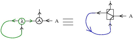
## Diagram: Quantum Circuit Equivalence
### Overview
The image depicts a diagram illustrating the equivalence between two quantum circuits. The diagram shows a circuit on the left side involving a parameter 'λ' and a controlled-NOT (CNOT) gate, and a circuit on the right side involving a different arrangement of gates and feedback loops. The equivalence is indicated by a triple equals sign ("===") between the two circuits.
### Components/Axes
The diagram consists of the following components:
* **Left Circuit:**
* A circle with the label "λ" inside.
* A CNOT gate (represented by a circle with a plus sign inside).
* Input/Output lines labeled "A".
* A green circular feedback loop.
* **Right Circuit:**
* A square gate with a diagonal line inside (representing a controlled operation).
* Input/Output lines labeled "A".
* A blue curved feedback loop.
* **Equivalence Indicator:**
* Three horizontal lines ("===") connecting the two circuits.
### Detailed Analysis or Content Details
The left circuit begins with an input "A" entering a CNOT gate. The output of the CNOT gate is then fed back into the input of a gate labeled "λ". The output of the "λ" gate is then fed back into the CNOT gate, forming a closed loop.
The right circuit takes an input "A" and feeds it into a square gate. The output of the square gate is then fed back into the input of the same gate, forming a closed loop.
The equivalence indicator ("===") suggests that these two circuits perform the same quantum operation.
### Key Observations
The diagram highlights a specific equivalence in quantum circuit design. The use of feedback loops in both circuits is notable. The "λ" gate on the left and the square gate on the right represent different quantum operations, but their combination with the feedback loops results in equivalent behavior.
### Interpretation
This diagram demonstrates a principle of quantum circuit simplification or transformation. It shows that different arrangements of quantum gates can achieve the same result. This is important for optimizing quantum algorithms and reducing the number of gates required to implement a specific operation. The equivalence likely relies on specific properties of the "λ" gate and the controlled operation within the square gate. The diagram suggests that the parameter "λ" plays a crucial role in establishing the equivalence. The diagram is a visual representation of a mathematical identity in quantum mechanics, showing that two seemingly different quantum operations are, in fact, equivalent. This type of equivalence is often used to simplify quantum circuits and make them more efficient.