## Diagram: Equivalence of Two System Representations
### Overview
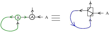
The image depicts two equivalent diagrams connected by the equivalence symbol (≡). The left diagram uses green and black elements, while the right uses blue and black. Both diagrams include directional arrows and symbolic components, suggesting a flow or process leading to a shared endpoint labeled "A".
### Components/Axes
- **Left Diagram**:
- **Green Loop**: A closed loop with a lambda symbol (λ) inside.
- **Black Circle**: Contains a triangle symbol (△) and is connected to the green loop.
- **Node "A"**: Final endpoint for both diagrams.
- **Right Diagram**:
- **Blue Loop**: A closed loop with a square containing a triangle (△) inside.
- **Node "A"**: Final endpoint, identical to the left diagram.
- **Equivalence Symbol (≡)**: Connects the two diagrams, indicating they represent the same system or concept.
### Detailed Analysis
- **Left Diagram Flow**:
1. The green loop (λ) feeds into the black circle (△).
2. The black circle directs output to node "A".
- **Right Diagram Flow**:
1. The blue loop (△ inside a square) feeds into node "A".
- **Symbolic Relationships**:
- The lambda (λ) in the left diagram may represent a variable, function, or parameter.
- The triangle (△) in both diagrams could symbolize a transformation, operation, or state.
- The square enclosing the triangle in the right diagram might denote a constrained or modified version of the triangle’s function.
### Key Observations
1. **Equivalence**: The diagrams are structurally distinct but functionally equivalent, as denoted by ≡.
2. **Color Coding**:
- Green (left) and blue (right) loops differentiate the two representations.
- Black elements (triangle, node "A") are consistent across both diagrams.
3. **Directionality**: All arrows point toward node "A", emphasizing it as the terminal state or output.
### Interpretation
The diagrams likely represent two equivalent mathematical, computational, or logical systems. The left diagram’s use of λ and △ suggests a parameter-driven process, while the right diagram’s square-with-triangle may indicate a structured or constrained version of the same process. The equivalence implies that despite differences in representation (e.g., symbolic vs. geometric), both systems achieve the same outcome at node "A". This could reflect principles in fields like category theory, computer science (e.g., equivalent code paths), or physics (e.g., equivalent force diagrams).
No numerical data or trends are present; the focus is on symbolic and structural equivalence.