\n
## Diagram: System Architecture - Broadcast and Selection
### Overview
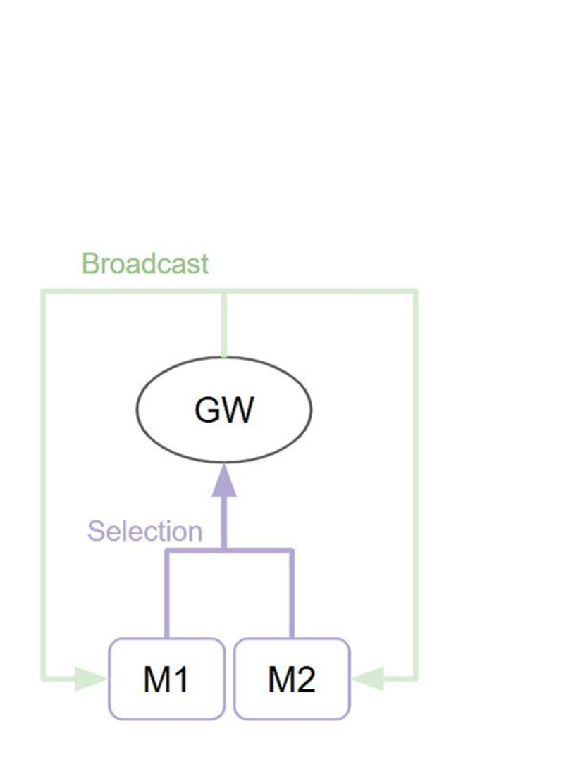
The image depicts a simplified system architecture diagram illustrating a broadcast mechanism and a selection process. It shows a Gateway (GW) receiving a broadcast signal and then a selection process directing signals to two Modules, M1 and M2. The diagram uses shapes (ellipse and rectangles) and arrows to represent components and data flow.
### Components/Axes
* **GW:** Gateway - Represented by an ellipse.
* **M1:** Module 1 - Represented by a rectangle.
* **M2:** Module 2 - Represented by a rectangle.
* **Broadcast:** Label indicating the input signal to the Gateway.
* **Selection:** Label indicating the process directing signals from the Gateway to the Modules.
* **Arrows:** Indicate the direction of data flow.
### Detailed Analysis or Content Details
The diagram shows the following data flow:
1. A "Broadcast" signal enters the system, directed towards the "GW" (Gateway). This is indicated by a light green arrow originating from the top of the diagram and pointing towards the ellipse representing the Gateway.
2. The Gateway (GW) then sends a "Selection" signal downwards, splitting into two separate arrows.
3. One arrow from the "Selection" process points to "M1" (Module 1).
4. The other arrow from the "Selection" process points to "M2" (Module 2).
5. There is a feedback loop from M2 to the GW, indicated by a light green arrow.
### Key Observations
* The diagram highlights a one-to-many relationship, where a single broadcast signal is processed by the Gateway and then distributed to multiple modules (M1 and M2).
* The feedback loop from M2 to GW suggests a potential control or acknowledgement mechanism.
* The diagram is highly abstract and does not provide any quantitative data or specific details about the functionality of each component.
### Interpretation
This diagram likely represents a system where a central Gateway receives a broadcast message and then selectively forwards it to specific modules based on some criteria. The "Selection" process could involve filtering, routing, or prioritization of messages. The feedback loop from M2 to GW suggests that M2 can provide information back to the Gateway, potentially influencing future selections or acknowledging receipt of the broadcast. The diagram is a high-level architectural overview and would require further documentation to understand the specific implementation details and the logic behind the selection process. It is a conceptual illustration rather than a detailed technical specification.