## Technical Diagram: Robotic Control System with Water Tank and Reservoir Network
### Overview
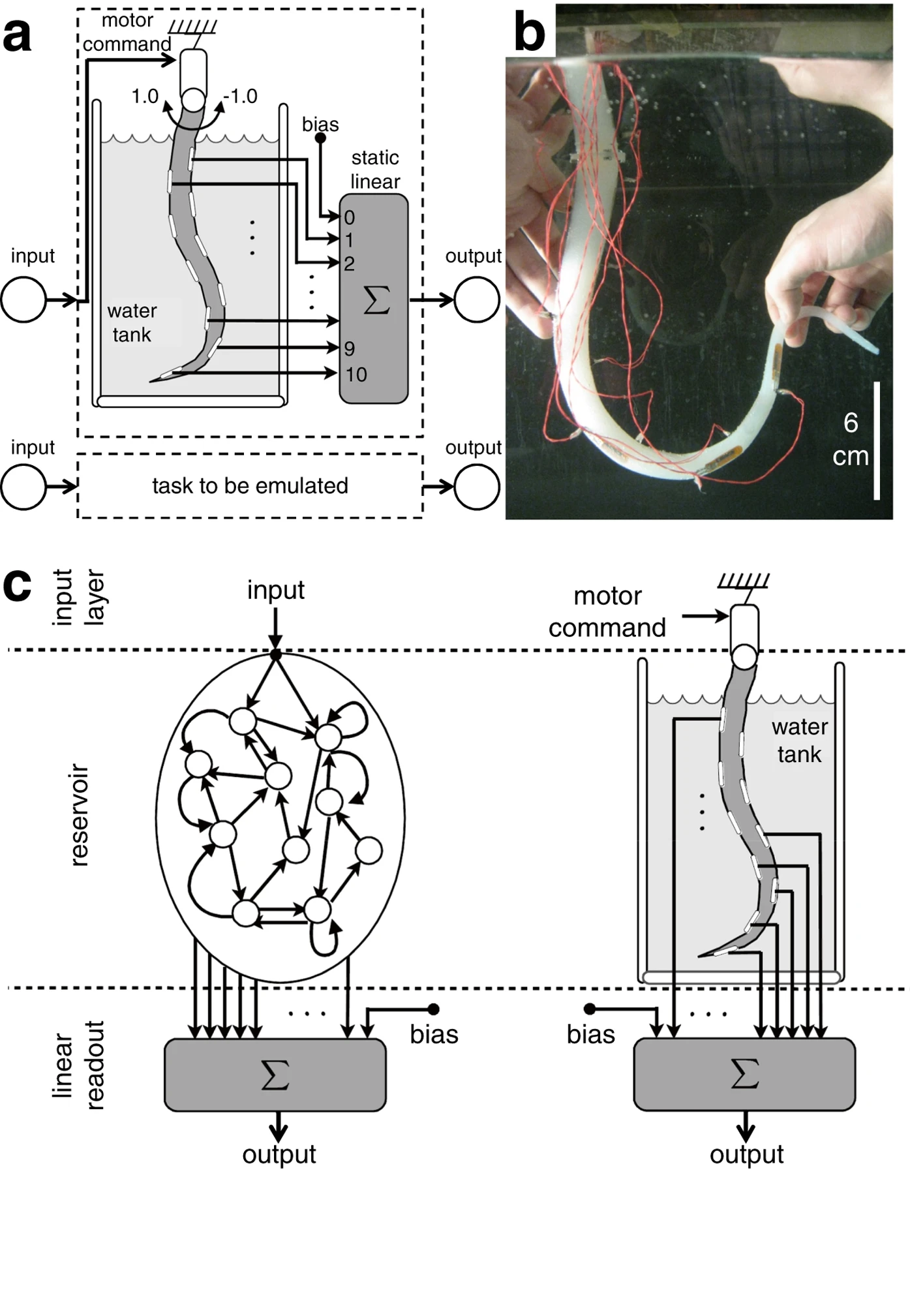
The image comprises three components:
1. **Part A**: A schematic of a water tank system with motor control, static linear processing, and feedback loops.
2. **Part B**: A photograph of a physical setup with a flexible tube, red wires, and human interaction.
3. **Part C**: A schematic of a reservoir network with input/output layers and dynamic connections.
---
### Components/Axes
#### Part A (Water Tank System)
- **Labels**:
- Input: Circular node labeled "input" (left side).
- Motor command: Arrows labeled "motor command" with range **-1.0 to 1.0**.
- Water tank: Gray rectangle with wavy lines representing water.
- Bias: Arrows labeled "bias" connecting to static linear.
- Static linear: Rectangular block labeled "static linear" with values **0 to 10** (vertical axis).
- Output: Circular node labeled "output" (right side).
- **Flow**:
- Input → Motor command → Water tank → Static linear (summation block Σ) → Output.
- Feedback loop: Output connects back to input via "task to be emulated" (dashed box).
#### Part B (Physical Setup)
- **Labels**:
- Flexible tube: White tube with red wires attached.
- Scale: Vertical ruler marked **6 cm**.
- Hands: Two hands manipulating the tube.
- **Details**:
- Red wires connect to the tube, suggesting electrical or mechanical actuation.
- Background: Dark surface with reflections, likely a lab environment.
#### Part C (Reservoir Network)
- **Labels**:
- Input layer: Circular nodes labeled "input" (top).
- Reservoir: Network of interconnected nodes with arrows indicating dynamic connections.
- Linear readout: Rectangular block labeled "linear readout" with summation block Σ.
- Output: Circular node labeled "output" (bottom).
- **Flow**:
- Input → Reservoir (non-linear dynamics) → Linear readout → Output.
---
### Detailed Analysis
#### Part A
- **Motor Command**: Range **-1.0 to 1.0** suggests bidirectional control (e.g., forward/backward motion).
- **Static Linear**: Values **0 to 10** likely represent sensor readings (e.g., water level, pressure) or control parameters.
- **Feedback Loop**: Output connects to input, implying closed-loop control for task emulation.
#### Part B
- **Flexible Tube**: 6 cm length with red wires indicates a physical actuator or sensor.
- **Human Interaction**: Hands adjusting the tube suggest manual calibration or testing.
#### Part C
- **Reservoir Network**: Nodes with arrows represent dynamic, possibly stochastic connections (e.g., neural network).
- **Linear Readout**: Summation block Σ aggregates reservoir outputs with bias for final output.
---
### Key Observations
1. **Integration of Systems**:
- Part A (control system) and Part C (reservoir network) are linked via input/output nodes, suggesting a hybrid control strategy.
2. **Physical Implementation**:
- Part B demonstrates real-world application, with the flexible tube acting as a mechanical interface for the control system.
3. **Scalability**:
- Static linear values (0–10) and motor command range (-1.0 to 1.0) imply modular design for adaptability.
---
### Interpretation
- **Control Mechanism**:
The system uses motor commands to adjust the water tank's position, with feedback from the static linear component to refine the output. The reservoir network in Part C likely processes complex inputs (e.g., environmental data) to optimize control.
- **Practical Application**:
The physical setup in Part B validates the schematic, showing how the flexible tube interacts with the system. The 6 cm scale suggests precise spatial requirements.
- **Dynamic Behavior**:
The reservoir network’s non-linear connections (Part C) enable adaptive responses, while the static linear component provides stable reference points.
This system appears to model a closed-loop robotic control framework, combining mechanical actuation, sensor feedback, and neural-like processing for task emulation.