## Diagram: Transformer Block Pruning
### Overview
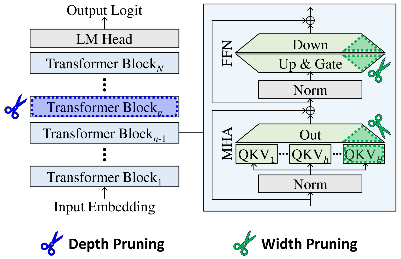
The image is a diagram illustrating the architecture of a Transformer model and two pruning techniques: depth pruning and width pruning. The diagram shows the flow of data through the model, from input embedding to output logit, and highlights the components affected by each pruning method.
### Components/Axes
* **Overall Structure:** The diagram depicts a Transformer model consisting of multiple Transformer Blocks stacked sequentially.
* **Input:** Input Embedding
* **Output:** Output Logit
* **Transformer Blocks:** A series of blocks labeled "Transformer Block₁", "Transformer Blockₙ₋₁", "Transformer Blockₙ", and "Transformer Blockₙ".
* **LM Head:** Located above the last Transformer Block.
* **MHA (Multi-Head Attention):** A block containing "Norm", "QKV₁", "QKVₕ", "QKVᴴ", and "Out".
* **FFN (Feed Forward Network):** A block containing "Norm", "Up & Gate", and "Down".
* **Depth Pruning:** Indicated by a blue scissors icon next to "Transformer Blockₙ".
* **Width Pruning:** Indicated by a green scissors icon next to the "Out" block in MHA and the "Up & Gate" and "Down" blocks in FFN.
### Detailed Analysis
* **Data Flow:** The data flows from the "Input Embedding" upwards through the "Transformer Blocks", then to the "LM Head", and finally to the "Output Logit".
* **Transformer Block Details:** Each Transformer Block is connected to an MHA and FFN block. The output of the MHA and FFN blocks are added to the main data flow.
* **MHA Block:** The MHA block contains a "Norm" layer at the bottom, followed by a series of "QKV" blocks (QKV₁, QKVₕ, QKVᴴ) and an "Out" block.
* **FFN Block:** The FFN block contains a "Norm" layer at the bottom, followed by "Up & Gate" and "Down" blocks.
* **Depth Pruning:** The blue scissors icon indicates that "Transformer Blockₙ" is being pruned.
* **Width Pruning:** The green scissors icon indicates that the "Out" block in MHA and the "Up & Gate" and "Down" blocks in FFN are being pruned. The pruned regions are marked with a green dotted pattern.
### Key Observations
* The diagram highlights the modular structure of the Transformer model.
* Depth pruning involves removing entire Transformer Blocks.
* Width pruning involves removing parts of the MHA and FFN blocks.
* The diagram shows the specific components targeted by each pruning technique.
### Interpretation
The diagram illustrates two common techniques for reducing the size and computational cost of Transformer models: depth pruning and width pruning. Depth pruning reduces the number of layers in the model, while width pruning reduces the size of the individual layers. The diagram shows that depth pruning targets entire Transformer Blocks, while width pruning targets specific components within the MHA and FFN blocks. This suggests that width pruning can be used to fine-tune the model's size and performance without completely removing entire layers. The green dotted pattern indicates the portion of the blocks that are being pruned.