\n
## Diagram: Transformer Model Pruning
### Overview
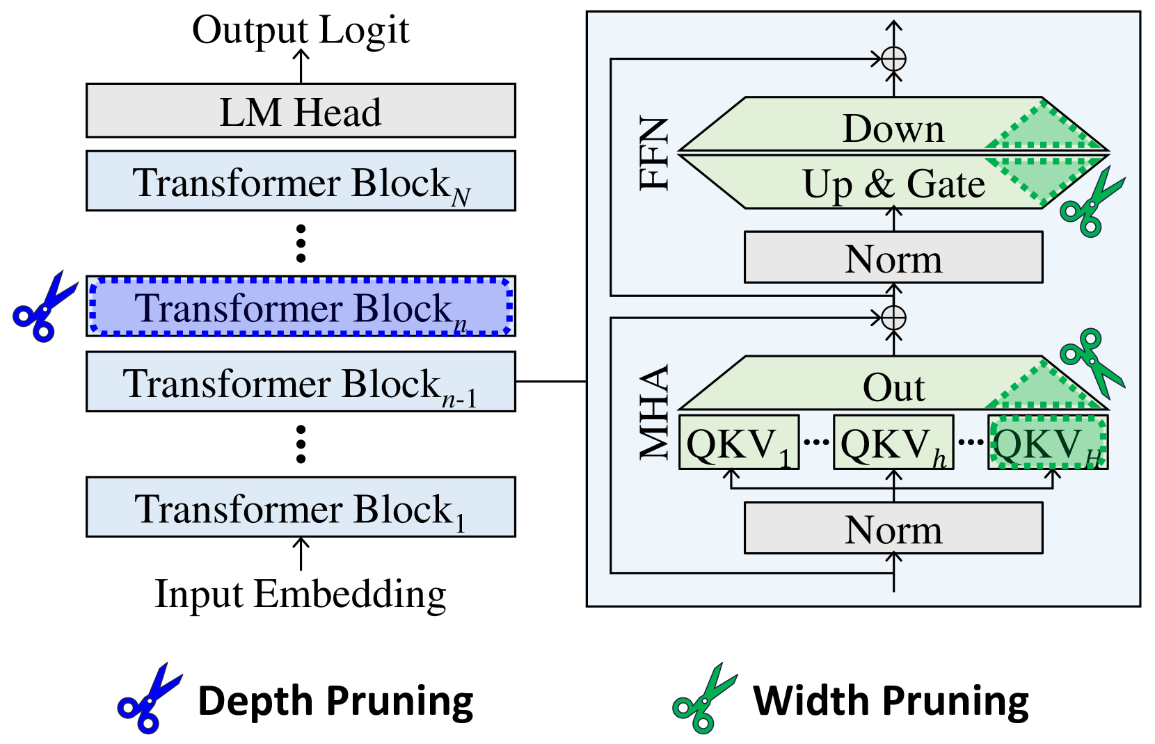
The image depicts a diagram illustrating depth and width pruning techniques applied to a Transformer model. The left side shows the standard Transformer architecture with stacked Transformer Blocks, while the right side demonstrates how pruning affects the Feed Forward Network (FFN) and Multi-Head Attention (MHA) layers. Scissors icons indicate the pruning locations.
### Components/Axes
The diagram consists of two main sections:
* **Left Side:** Represents the standard Transformer architecture. Components include: Input Embedding, Transformer Blocks (numbered 1 to N), LM Head, and Output Logit.
* **Right Side:** Illustrates pruning within the FFN and MHA layers. Components include: MHA (with QKV representations), Norm layers, Up & Gate, Down, and Out.
* **Pruning Indicators:** Scissors icons represent the pruning locations. There are two labels for the pruning types: "Depth Pruning" (left) and "Width Pruning" (right).
### Detailed Analysis or Content Details
**Left Side (Depth Pruning):**
* The diagram shows a stack of Transformer Blocks, labeled Transformer Block<sub>1</sub> through Transformer Block<sub>N</sub>.
* The ellipsis (...) indicates that there are multiple Transformer Blocks between the labeled ones.
* A scissors icon is placed over Transformer Block<sub>n</sub>, indicating that this block is being pruned (removed) for depth pruning.
* The flow is from Input Embedding -> Transformer Blocks -> LM Head -> Output Logit.
**Right Side (Width Pruning):**
* The diagram shows two main components: FFN and MHA.
* **MHA:** Contains multiple QKV (Query, Key, Value) representations, labeled QKV<sub>1</sub> through QKV<sub>h</sub>. The number of QKV representations is denoted by 'h'.
* A "Norm" layer precedes the MHA.
* An "Out" layer follows the MHA.
* A scissors icon is placed over a portion of the QKV representations within the MHA, indicating width pruning.
* **FFN:** Contains "Up & Gate", "Norm", and "Down" layers.
* A scissors icon is placed over the "Up & Gate" layer, indicating width pruning.
* The flow within the FFN is Norm -> Up & Gate -> Down.
* The FFN and MHA are connected via addition (represented by the circle with a plus sign).
### Key Observations
* Depth pruning removes entire Transformer Blocks, reducing the model's depth.
* Width pruning removes parts of the FFN and MHA layers, reducing the model's width.
* The pruning is visually represented by scissors cutting through the respective layers.
* The diagram clearly distinguishes between depth and width pruning strategies.
### Interpretation
The diagram illustrates two common techniques for reducing the size and computational cost of Transformer models: depth pruning and width pruning. Depth pruning simplifies the model by removing entire layers, while width pruning reduces the dimensionality of the layers. Both techniques aim to create a smaller, more efficient model without significantly sacrificing performance. The use of scissors as a visual metaphor effectively conveys the idea of removing parts of the network. The diagram suggests that pruning can be applied selectively to different parts of the model, allowing for a fine-grained control over the trade-off between model size and accuracy. The diagram does not provide any quantitative data on the effectiveness of these pruning techniques, but it clearly demonstrates the conceptual approach.