## Block Diagram: Hardware Architecture for Data Processing
### Overview
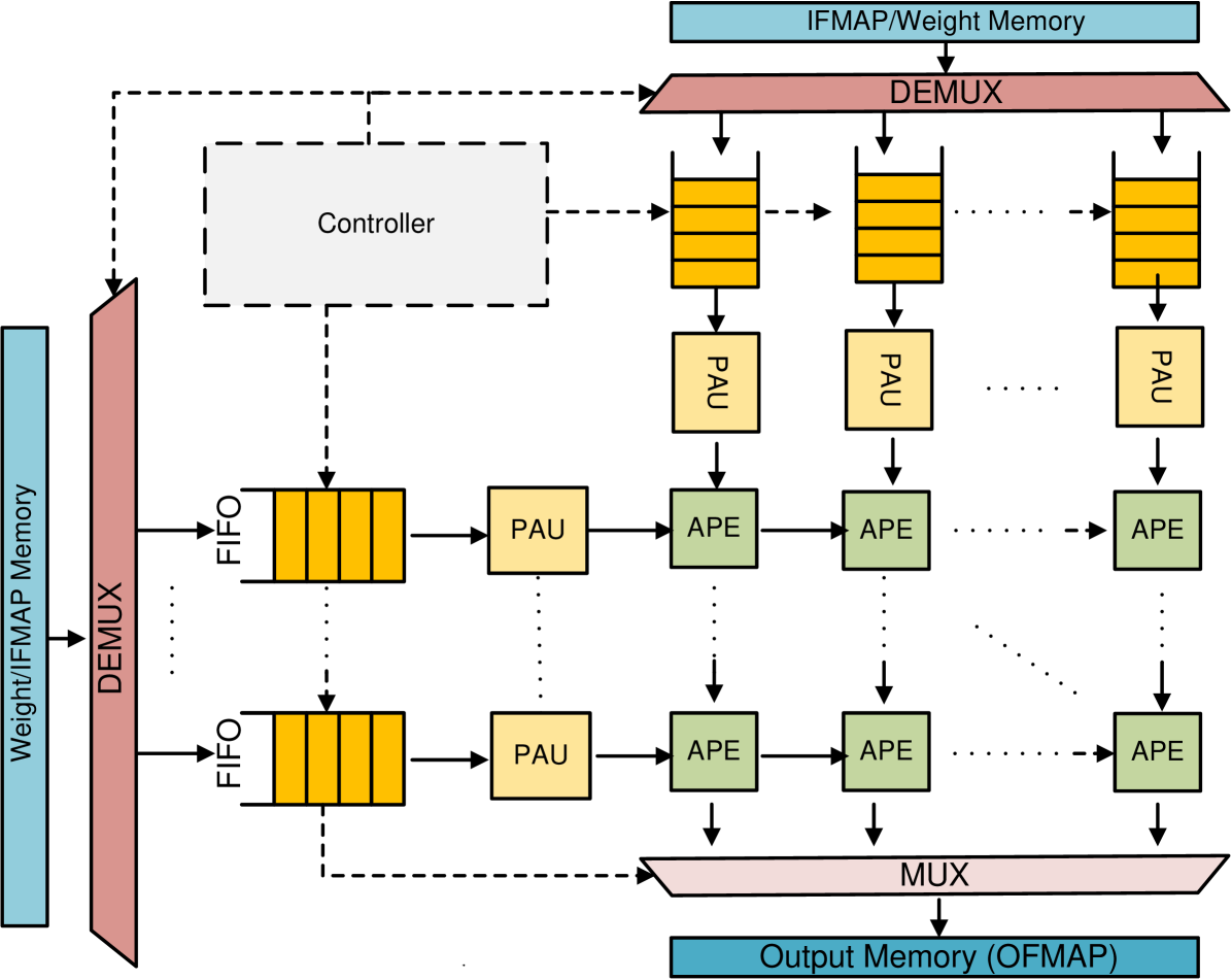
This diagram illustrates a hardware architecture designed for high-performance data processing, likely an accelerator for neural network operations (such as matrix multiplication). The system utilizes a grid-based processing array (systolic array) fed by memory modules, managed by a central controller, and utilizing buffers (FIFOs) to synchronize data flow.
### Components/Axes
* **Memory Modules (Blue Rectangles):**
* **Top:** IFMAP/Weight Memory
* **Left:** Weight/IFMAP Memory
* **Bottom:** Output Memory (OFMAP)
* **Routing Logic (Red Trapezoids):**
* **Top:** DEMUX (Distributes data from top memory to the array)
* **Left:** DEMUX (Distributes data from left memory to the array)
* **Bottom:** MUX (Aggregates data from the array to the output memory)
* **Buffers (Yellow Rectangles with lines):**
* **FIFO:** First-In-First-Out queues used to stage data before processing.
* **Processing Units:**
* **PAU (Yellow Squares):** Processing/Arithmetic Units.
* **APE (Green Squares):** Array Processing Elements.
* **Control:**
* **Controller (Dashed Box):** Located in the top-left quadrant, managing the flow of data.
### Detailed Analysis
#### Data Flow and Connectivity
1. **Input Path (Top):** Data flows from the **IFMAP/Weight Memory** into the top **DEMUX**. The DEMUX distributes data into a row of vertical **FIFO** buffers. These FIFOs feed into a row of **PAU** units, which then pass data into the top row of the **APE** grid.
2. **Input Path (Left):** Data flows from the **Weight/IFMAP Memory** into the left **DEMUX**. The DEMUX distributes data into a column of horizontal **FIFO** buffers. These FIFOs feed into a column of **PAU** units, which then pass data into the leftmost column of the **APE** grid.
3. **Processing Grid:** The **APE** units (green) are arranged in a 2D grid. Data flows from the top PAUs downwards and from the left PAUs rightwards through the APEs. The ellipsis ("...") indicates that the grid is scalable and larger than the visible 3x2 representation.
4. **Output Path:** The bottom row of **APE** units feeds into the bottom **MUX**. This MUX aggregates the processed data and sends it to the **Output Memory (OFMAP)**.
5. **Control Logic:** The **Controller** (dashed box) has dashed control lines extending to:
* The top DEMUX.
* The top row of FIFOs.
* The left column of FIFOs.
* The bottom MUX.
### Key Observations
* **Scalability:** The use of ellipsis (...) in both the horizontal and vertical directions indicates that the architecture is designed to be modular and scalable to larger array sizes.
* **Symmetry:** The design is highly symmetrical, with inputs coming from two orthogonal directions (top and left) and converging into a processing grid.
* **Color Coding:**
* **Blue:** Memory storage.
* **Red:** Data routing (Multiplexing/Demultiplexing).
* **Yellow:** Buffering and initial processing (FIFO/PAU).
* **Green:** Core computation (APE).
* **Control Hierarchy:** The controller acts as the central orchestrator, ensuring the FIFOs and routing logic are synchronized.
### Interpretation
This diagram represents a **Systolic Array Architecture**, a standard design pattern for Deep Learning accelerators (like TPUs or NPU cores).
* **Functionality:** The system is designed to perform Matrix-Matrix multiplication. One input (e.g., Weights) is streamed from the left, and the other (e.g., Input Feature Maps - IFMAP) is streamed from the top.
* **Data Movement:** The "systolic" nature refers to the rhythmic, pulse-like movement of data through the APE grid. Each APE likely performs a Multiply-Accumulate (MAC) operation.
* **Efficiency:** By using FIFOs and PAUs, the architecture decouples memory access from computation, allowing the APE grid to remain saturated with data, thereby maximizing throughput and minimizing memory latency.
* **Peircean Investigative Note:** The presence of both "IFMAP/Weight" and "Weight/IFMAP" labels on the input memories suggests the architecture is flexible; it can swap the roles of the inputs depending on the specific layer of the neural network being computed (e.g., weight-stationary vs. output-stationary dataflows).