\n
## Diagram: Dataflow Architecture for a Processing Unit
### Overview
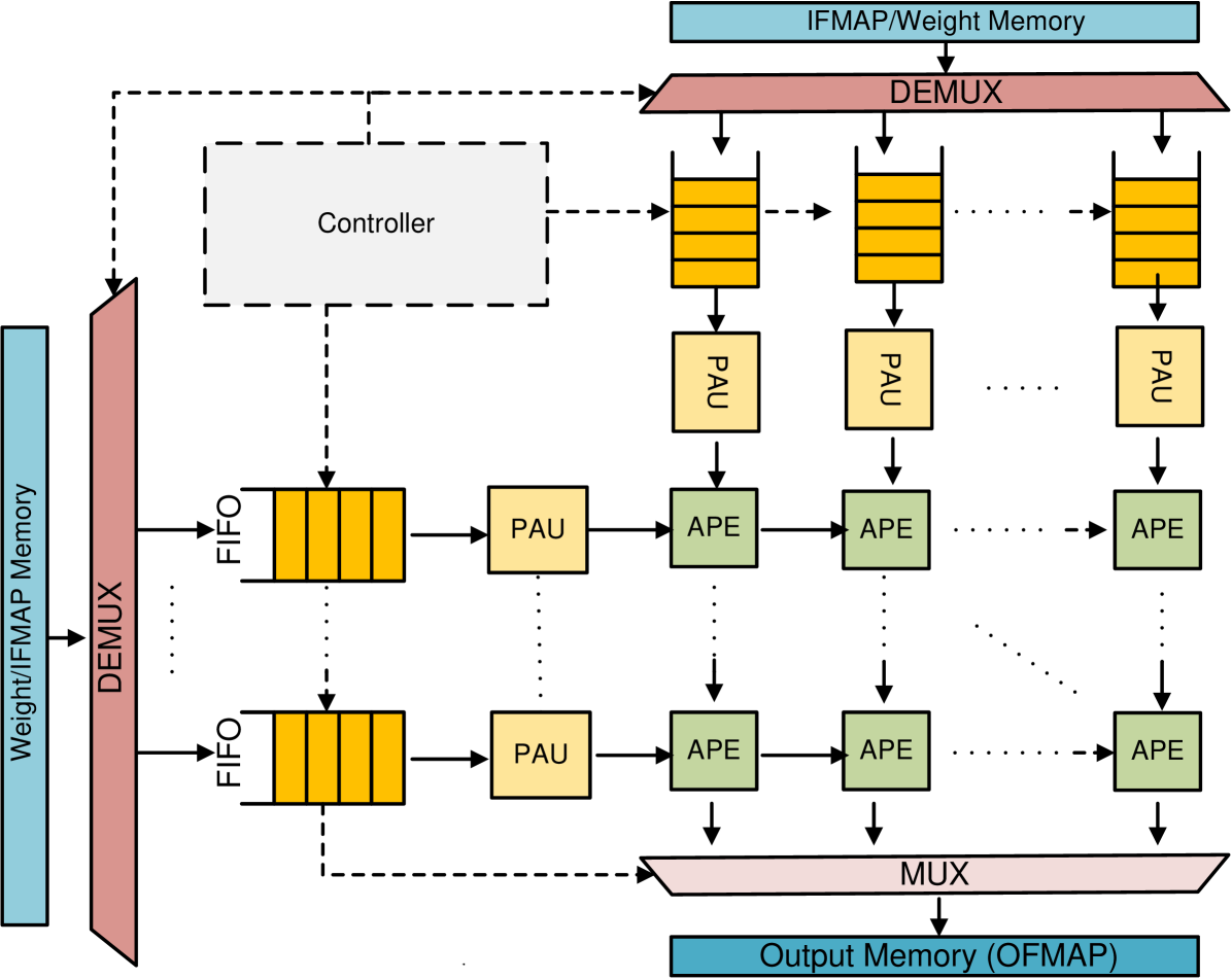
The image depicts a dataflow architecture for a processing unit, likely a specialized accelerator for neural network operations. It illustrates the flow of data from input feature maps and weights, through processing elements (PAUs and APEs), and finally to output memory. The diagram emphasizes parallel processing and the role of a controller in managing the data flow.
### Components/Axes
The diagram consists of the following key components:
* **Weight/IFMAP Memory:** Located on the left side, serving as the primary input source for both weights and input feature maps (IFMAP).
* **IFMAP/Weight Memory:** Located at the top, providing weights to the processing elements.
* **DEMUX (Demultiplexer):** Two instances are present, one for the Weight/IFMAP Memory and one for the IFMAP/Weight Memory. These distribute data to multiple FIFO queues.
* **FIFO (First-In, First-Out) Queues:** These act as buffers between the memory and the processing units. Multiple FIFO queues are shown, receiving data from the DEMUX.
* **PAU (Processing Array Unit):** These units perform initial processing on the data received from the FIFO queues.
* **APE (Arithmetic Processing Element):** These units perform further processing on the output of the PAUs. Multiple APEs are chained together.
* **MUX (Multiplexer):** Located at the bottom, combining the outputs from the APEs into a single output stream.
* **Output Memory (OFMAP):** Located at the bottom, storing the final output feature maps.
* **Controller:** A dashed box in the center-left, responsible for coordinating the data flow between the various components.
There are no explicit axes in this diagram, as it represents a system architecture rather than a data plot.
### Detailed Analysis or Content Details
The diagram illustrates a parallel processing architecture.
1. **Data Input:** Weights and IFMAPs are read from the Weight/IFMAP Memory and IFMAP/Weight Memory.
2. **Demultiplexing:** The DEMUX distributes the data to multiple FIFO queues. The number of FIFO queues is not explicitly stated, but appears to be at least 4.
3. **Buffering:** The FIFO queues buffer the data before it is fed to the PAUs.
4. **Initial Processing (PAU):** The PAUs perform an initial stage of processing on the data.
5. **Further Processing (APE):** The output of the PAUs is then fed to a chain of APEs for further processing. The number of APEs in the chain is not explicitly stated, but appears to be multiple.
6. **Multiplexing:** The MUX combines the outputs from the APEs.
7. **Output:** The final output is written to the Output Memory (OFMAP).
8. **Control:** The Controller manages the entire data flow, coordinating the operation of the DEMUX, FIFO queues, PAUs, APEs, and MUX.
The dashed lines indicate control signals or data flow managed by the Controller. The diagram suggests a highly parallel architecture, with multiple PAUs and APEs operating concurrently.
### Key Observations
* The architecture is designed for parallel processing, with multiple processing elements operating simultaneously.
* The FIFO queues provide buffering to handle variations in data rates between the memory and the processing units.
* The Controller plays a crucial role in coordinating the data flow and ensuring correct operation.
* The diagram does not specify the type of processing performed by the PAUs and APEs, but it is likely related to neural network operations such as convolution or matrix multiplication.
* The use of DEMUX and MUX suggests a flexible architecture that can handle different data widths and formats.
### Interpretation
This diagram represents a specialized hardware accelerator designed for efficient processing of data, likely for deep learning applications. The parallel architecture, combined with the buffering provided by the FIFO queues and the coordination of the Controller, allows for high throughput and low latency. The separation of processing into PAUs and APEs suggests a pipelined architecture, where data is processed in stages. The overall design emphasizes maximizing computational efficiency and minimizing data movement, which are critical for performance in deep learning workloads. The diagram highlights a common approach to designing hardware accelerators for neural networks, focusing on parallel processing and efficient data flow. The absence of specific numerical values or performance metrics suggests that the diagram is intended to illustrate the overall architecture rather than provide detailed performance characteristics.