## Directed Acyclic Graph: Dependency Network
### Overview
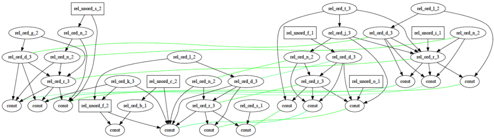
The image is a directed acyclic graph (DAG) representing a dependency network. Nodes in the graph are labeled with strings like "rel_ord_g_2", "rel_unord_s_2", and "const". Edges, represented by arrows, indicate dependencies between nodes. Some edges are black, while others are green. Nodes with rounded rectangles are labeled "rel_ord_...", while nodes with square rectangles are labeled "rel_unord_...". The "const" nodes appear to be terminal nodes.
### Components/Axes
* **Nodes:** Represented by ovals and rectangles.
* Ovals: Labeled as "rel_ord_..."
* Rectangles: Labeled as "rel_unord_..."
* Ovals: Labeled as "const"
* **Edges:** Represented by arrows, indicating the direction of dependency.
* Black Arrows: Standard dependency flow.
* Green Arrows: Represent a different type of dependency or relationship.
* **Labels:** Text strings within the nodes, identifying the type and specific instance of the relationship or constant.
### Detailed Analysis or Content Details
**Left Branch:**
* Top: "rel_unord_s_2" (rectangle)
* Below "rel_unord_s_2": "rel_ord_g_2" (oval) and "rel_ord_n_2" (oval)
* Below "rel_ord_g_2" and "rel_ord_n_2": "rel_ord_d_3" (oval) and "rel_ord_n_2" (oval)
* Below "rel_ord_d_3" and "rel_ord_n_2": "rel_ord_r_3" (oval)
* Bottom: Three "const" nodes (ovals).
**Middle Branch:**
* Top: "rel_ord_l_2" (oval)
* Below "rel_ord_l_2": "rel_ord_k_3" (oval), "rel_unord_c_2" (rectangle), "rel_ord_n_2" (oval), and "rel_ord_d_3" (oval)
* Below: "rel_unord_f_2" (rectangle), "rel_ord_b_1" (oval), "rel_ord_r_3" (oval), and "rel_ord_s_1" (oval)
* Bottom: Four "const" nodes (ovals).
**Right Branch:**
* Top: "rel_ord_t_3" (oval) and "rel_ord_l_2" (oval)
* Below "rel_ord_t_3": "rel_unord_f_1" (rectangle) and "rel_ord_j_3" (oval) and "rel_ord_d_3" (oval)
* Below "rel_ord_l_2": "rel_unord_i_1" (rectangle) and "rel_ord_n_2" (oval)
* Below: "rel_ord_n_2" (oval), "rel_ord_d_3" (oval), and "rel_ord_r_3" (oval) and "rel_unord_o_1" (rectangle)
* Bottom: Four "const" nodes (ovals).
**Edge Types:**
* Black edges indicate a standard dependency.
* Green edges connect nodes across different branches, suggesting a more complex relationship. For example, a green edge connects "rel_ord_g_2" to one of the "const" nodes in the middle branch.
### Key Observations
* The graph has a hierarchical structure, with nodes at the top influencing nodes below.
* The "const" nodes are terminal nodes, indicating the end of a dependency chain.
* The "rel_unord_..." nodes appear to act as connectors or aggregators, influencing multiple downstream nodes.
* The green edges suggest cross-dependencies or relationships between different parts of the graph.
### Interpretation
The DAG represents a complex system of dependencies, likely within a software or data processing pipeline. The "rel_ord_..." nodes represent ordered relationships, while "rel_unord_..." nodes represent unordered relationships. The "const" nodes likely represent constant values or final outputs. The green edges indicate a more complex interaction between different parts of the system, possibly representing data flow or control signals. The structure of the graph suggests a modular design, with different branches representing different components or modules. The interconnections between these modules, represented by the green edges, are crucial for the overall system behavior.