## Diagram: Directed Dependency Graph of Relational Entities
### Overview
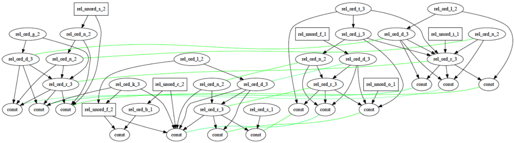
This image displays a complex directed graph representing dependencies between various relational entities. The graph is organized into two primary clusters (left and right) that are interconnected by a series of green lines. The nodes are categorized into two visual types: ovals (representing ordered relations, labeled `rel_ord_...`) and rectangles (representing unordered relations, labeled `rel_unord_...`). The graph terminates at the bottom in multiple `const` (constant) nodes.
### Components/Axes
* **Nodes (Ovals):** Labeled `rel_ord_[letter]_[number]`. These represent ordered relations.
* **Nodes (Rectangles):** Labeled `rel_unord_[letter]_[number]`. These represent unordered relations.
* **Nodes (Small Ovals):** Labeled `const`. These represent terminal constant values.
* **Edges (Black Arrows):** Represent primary directed dependencies or hierarchical flow.
* **Edges (Green Lines):** Represent secondary or cross-cluster relationships/constraints.
**List of Unique Labels:**
* `rel_unord_s_2`
* `rel_ord_g_2`
* `rel_ord_n_2`
* `rel_ord_d_3`
* `rel_ord_r_3`
* `rel_ord_l_2`
* `rel_ord_k_3`
* `rel_unord_c_2`
* `rel_ord_b_1`
* `rel_unord_f_2`
* `rel_ord_s_1`
* `rel_ord_t_3`
* `rel_unord_f_1`
* `rel_ord_j_3`
* `rel_unord_i_1`
* `rel_unord_o_1`
### Detailed Analysis
#### Left Cluster
* **Top-most element:** `rel_unord_s_2` (rectangle) acts as a root, pointing downward to `rel_ord_n_2`.
* **Mid-section:** `rel_ord_g_2` and `rel_ord_n_2` feed into `rel_ord_d_3` and `rel_ord_r_3`.
* **Lower-section:** `rel_ord_l_2` (positioned centrally between the two main clusters) feeds into `rel_ord_d_3` and `rel_ord_r_3` in the left cluster.
* **Bottom-section:** `rel_ord_k_3` feeds into `rel_ord_b_1` and `const`. `rel_unord_c_2` feeds into `const` and `rel_ord_r_3`. `rel_unord_f_2` feeds into `const`.
#### Right Cluster
* **Top-most element:** `rel_ord_t_3` (oval) acts as a root, pointing to `rel_ord_j_3` and `rel_ord_d_3`.
* **Mid-section:** `rel_unord_f_1` (rectangle) feeds into `rel_ord_n_2` and `rel_ord_d_3`. `rel_ord_j_3` feeds into `rel_ord_n_2`, `rel_ord_d_3`, and `rel_ord_r_3`.
* **Right-most elements:** `rel_unord_i_1` (rectangle) feeds into `rel_ord_r_3`. `rel_ord_l_2` (top right) feeds into `rel_ord_d_3` and `rel_ord_r_3`.
* **Bottom-section:** `rel_unord_o_1` (rectangle) feeds into `rel_ord_r_3` and `const`.
#### Green Line Connections
* The green lines originate from various `rel_ord_` nodes in the left cluster and terminate at `rel_ord_` nodes in the right cluster, and vice versa.
* These lines appear to bypass the hierarchical black-arrow structure, suggesting non-hierarchical constraints or synchronization points between the two sub-graphs.
### Key Observations
* **Repetition:** Several labels (e.g., `rel_ord_n_2`, `rel_ord_d_3`, `rel_ord_r_3`, `rel_ord_l_2`) appear multiple times across the graph. This indicates that the graph is likely a flattened representation of a recursive structure or a system where specific relation types are instantiated multiple times.
* **Hierarchy:** The flow is strictly top-to-bottom, with `const` nodes consistently appearing at the lowest level of the hierarchy.
* **Structural Asymmetry:** The left cluster is more densely populated with `rel_unord` (rectangular) nodes at the top, while the right cluster is more heavily populated with `rel_ord` (oval) nodes.
### Interpretation
This diagram is characteristic of a **dependency graph** or **abstract syntax tree (AST)** used in compiler design, database query optimization, or formal logic verification.
* **`rel_ord` vs `rel_unord`:** The distinction between ordered and unordered relations suggests the system differentiates between operations where sequence matters (e.g., sequential execution, ordered lists) and operations where sequence is irrelevant (e.g., set operations, commutative logic).
* **`const` nodes:** These represent the "leaves" of the tree—literal values or base-case constants that require no further resolution.
* **Green Lines:** These are likely "cross-references" or "constraints." In a database query plan, these might represent join conditions or dependencies between different branches of a query tree that must be satisfied simultaneously.
* **Overall Logic:** The graph demonstrates a system where high-level relational definitions (`rel_unord_s_2`, `rel_ord_t_3`) are decomposed into smaller, repeated relational components (`rel_ord_d_3`, `rel_ord_r_3`) before finally resolving to constant values. The presence of multiple instances of the same label suggests that the underlying logic is modular and reusable.