## System Diagram: TEE Attestation Flow in Cloud Environment
### Overview
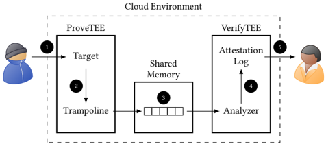
The image is a system diagram illustrating the flow of data and processes within a cloud environment for Trusted Execution Environment (TEE) attestation. It depicts the interaction between a prover (ProveTEE) and a verifier (VerifyTEE), mediated by shared memory, to establish trust.
### Components/Axes
* **Cloud Environment:** The entire system operates within a "Cloud Environment," indicated by a dashed-line box encompassing the ProveTEE and VerifyTEE components.
* **ProveTEE:** A component labeled "ProveTEE" on the left side of the diagram. It contains two sub-components:
* **Target:** The initial entry point for data, receiving input from an external actor.
* **Trampoline:** A process that receives data from the "Target" and forwards it to "Shared Memory."
* **VerifyTEE:** A component labeled "VerifyTEE" on the right side of the diagram. It contains two sub-components:
* **Analyzer:** Receives data from "Shared Memory" and processes it.
* **Attestation Log:** Receives data from the "Analyzer."
* **Shared Memory:** A component located between "ProveTEE" and "VerifyTEE," acting as a buffer or communication channel. It is represented as a box containing five smaller empty boxes.
* **Actors:**
* Left: A person wearing a hat and jacket, representing the data provider or initiator.
* Right: A person, representing the verifier or recipient of the attestation.
* **Numbered Steps:** The diagram includes numbered steps (1-5) indicating the flow of data:
1. Input from the left actor to the "Target" in "ProveTEE."
2. Data flow from "Target" to "Trampoline" within "ProveTEE."
3. Data flow from "Trampoline" to "Shared Memory."
4. Data flow from "Analyzer" to "Attestation Log" within "VerifyTEE."
5. Output from "Attestation Log" to the right actor.
### Detailed Analysis or Content Details
The diagram shows a sequential process:
1. **Step 1:** An actor (left) sends data to the "Target" within the "ProveTEE."
2. **Step 2:** The "Target" passes the data to the "Trampoline" within the "ProveTEE."
3. **Step 3:** The "Trampoline" sends data to the "Shared Memory." The "Shared Memory" is depicted as a buffer with five slots.
4. **Step 4:** The "Analyzer" in "VerifyTEE" receives data from the "Shared Memory" and processes it, sending the result to the "Attestation Log."
5. **Step 5:** The "Attestation Log" provides the final output to the actor on the right.
### Key Observations
* The diagram emphasizes the flow of data between "ProveTEE" and "VerifyTEE" through "Shared Memory."
* The numbered steps clearly outline the sequence of operations.
* The "Cloud Environment" boundary indicates that all components operate within a cloud infrastructure.
### Interpretation
The diagram illustrates a TEE attestation process in a cloud environment. The "ProveTEE" component generates data, which is then verified by the "VerifyTEE" component. The "Shared Memory" acts as an intermediary, potentially decoupling the "ProveTEE" and "VerifyTEE" processes. The "Attestation Log" likely stores the results of the verification process, providing evidence of the TEE's integrity. The diagram suggests a secure and verifiable execution environment within the cloud.