\n
## Diagram: Cloud Environment Attestation Flow
### Overview
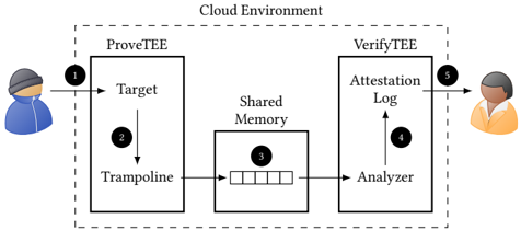
The image depicts a diagram illustrating a cloud environment attestation flow between a user and a cloud service. The flow involves two main components: ProveTEE and VerifyTEE, connected via shared memory. The diagram uses numbered arrows to indicate the sequence of operations.
### Components/Axes
The diagram consists of the following components:
* **Cloud Environment:** A dashed rectangle encompassing the entire process.
* **ProveTEE:** A rectangular block representing the trusted execution environment where the target application resides. Contains "Target" and "Trampoline" components.
* **VerifyTEE:** A rectangular block representing the trusted execution environment responsible for verifying the attestation. Contains "Attestation Log" and "Analyzer" components.
* **Shared Memory:** A rectangular block representing the shared memory space between ProveTEE and VerifyTEE. Contains a data structure represented as a series of rectangles.
* **User (Left):** A cartoon figure representing the user initiating the process.
* **Verifier (Right):** A cartoon figure representing the entity verifying the attestation.
* **Arrows (1-5):** Numbered arrows indicating the flow of data and control.
### Detailed Analysis or Content Details
The diagram illustrates the following flow:
1. **User to Target:** An arrow labeled "1" points from the user (left) to the "Target" component within ProveTEE. This represents the initial request or invocation of the target application.
2. **Target to Trampoline:** An arrow labeled "2" points from the "Target" component to the "Trampoline" component within ProveTEE. This indicates a transition or handover of control.
3. **Trampoline to Shared Memory:** An arrow labeled "3" points from the "Trampoline" component to the "Shared Memory". This represents writing attestation data into the shared memory. The data in shared memory is represented as a series of rectangles.
4. **Shared Memory to Analyzer:** An arrow labeled "4" points from the "Shared Memory" to the "Analyzer" component within VerifyTEE. This indicates the Analyzer reading the attestation data from shared memory.
5. **Analyzer to Verifier:** An arrow labeled "5" points from the "Analyzer" component to the verifier (right). This represents the final attestation result being delivered to the verifier.
### Key Observations
The diagram highlights a secure attestation process where the ProveTEE generates evidence of its state and writes it to shared memory. The VerifyTEE then reads this evidence and provides it to the verifier. The use of shared memory facilitates communication between the two trusted execution environments. The numbered arrows clearly define the sequence of operations.
### Interpretation
This diagram illustrates a typical architecture for remote attestation in a cloud environment. The ProveTEE component is responsible for generating a cryptographic attestation of the target application's state. This attestation is then securely transferred to the VerifyTEE component via shared memory. The VerifyTEE component analyzes the attestation and provides a verification result to the verifier. This process ensures that the verifier can trust the integrity of the target application running in the cloud environment. The use of a trampoline suggests a mechanism for transitioning between different security domains or privilege levels. The shared memory acts as a secure channel for exchanging sensitive attestation data. The diagram does not provide specific details about the attestation protocol or the cryptographic techniques used, but it provides a high-level overview of the attestation flow.