## Diagram: Cloud Environment Architecture
### Overview
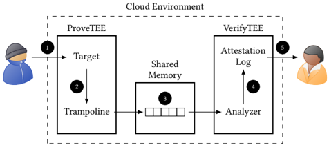
The diagram illustrates a cloud-based system architecture involving two primary components: **ProveTEE** and **VerifyTEE**, connected via a **Shared Memory** module. Two users (represented by avatars) interact with the system at different stages, with data flowing through labeled components.
### Components/Axes
1. **ProveTEE** (Left Box):
- **Target**: A component within ProveTEE, labeled with a downward arrow (2) pointing to **Shared Memory**.
- **Trampoline**: A sub-component within ProveTEE, connected to the Target via a bidirectional arrow.
- **User Interaction**: A blue-clad avatar (labeled "1") initiates the process by sending input to the Target.
2. **VerifyTEE** (Right Box):
- **Analyzer**: A component within VerifyTEE, connected to **Shared Memory** via a bidirectional arrow.
- **Attestation Log**: A sub-component within VerifyTEE, linked to the Analyzer via an upward arrow (4).
- **User Interaction**: An orange-clad avatar (labeled "5") receives output from the Attestation Log.
3. **Shared Memory**:
- A central module (labeled "3") with five horizontal slots, acting as a bridge between ProveTEE and VerifyTEE.
4. **Arrows**:
- Dashed arrows outline the cloud environment boundary.
- Solid arrows indicate data flow:
- User 1 → ProveTEE Target → Shared Memory (via Trampoline).
- Shared Memory → VerifyTEE Analyzer → Attestation Log → User 5.
### Detailed Analysis
- **Labels**: All textual elements are explicitly labeled (e.g., "ProveTEE," "VerifyTEE," "Shared Memory").
- **Flow Direction**:
- Data originates from User 1, enters ProveTEE, and is processed through the Target and Trampoline before being stored in Shared Memory.
- Shared Memory is then accessed by VerifyTEE’s Analyzer, which generates an Attestation Log shared back with User 5.
- **Shared Memory Structure**: Five horizontal slots suggest a fixed-capacity buffer or log for storing intermediate data.
### Key Observations
1. **Bidirectional Flow**: The Trampoline and Analyzer components have bidirectional arrows, implying two-way communication or validation.
2. **User Roles**:
- User 1 (blue) initiates data input.
- User 5 (orange) receives verification results, suggesting a client-server or auditor-auditee relationship.
3. **Security Focus**: Terms like "Attestation Log" and "Trampoline" imply cryptographic or secure data handling.
### Interpretation
This architecture likely represents a **secure enclave-based system** for data integrity verification.
- **ProveTEE** acts as a data-proving module, using the Trampoline to securely transfer data to Shared Memory.
- **VerifyTEE** validates the data’s authenticity via the Analyzer, which cross-references the Attestation Log stored in Shared Memory.
- The Shared Memory serves as a tamper-evident ledger, ensuring data consistency between ProveTEE and VerifyTEE.
- The separation of roles (User 1 vs. User 5) suggests a decentralized trust model, where different stakeholders independently verify data integrity.
The diagram emphasizes **modularity** and **security**, with clear demarcation between data generation, storage, and verification phases. The use of "Trampoline" and "Attestation Log" hints at cryptographic techniques like zero-knowledge proofs or secure multi-party computation.