## Diagram: Multi-Stage Encoder-Decoder Architecture with Attention Mechanisms
### Overview
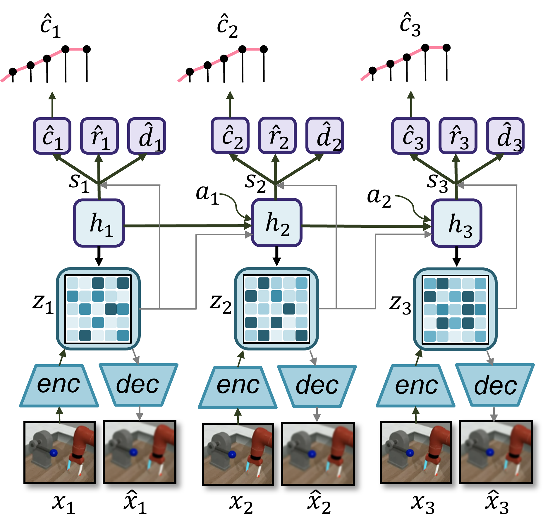
The diagram illustrates a three-stage sequential processing system with encoder-decoder blocks, attention mechanisms, and hidden layers. Each stage processes input data (x₁, x₂, x₃) through encoding (Z₁, Z₂, Z₃), hidden layers (h₁, h₂, h₃), and decoding to produce reconstructed outputs (x̂₁, x̂₂, x̂₃). The system includes attention components (a₁, a₂) and auxiliary variables (s₁, s₂, s₃, c₁, c₂, c₃, r₁, r₂, r₃, d₁, d₂, d₃).
### Components/Axes
1. **Top Layer (c₁, c₂, c₃)**:
- Three parallel sequences with circular nodes connected by pink lines.
- Labels: c₁, c₂, c₃ (possibly control parameters or context vectors).
2. **Hidden Layers (h₁, h₂, h₃)**:
- Three interconnected blue squares with green arrows.
- Positioned between encoder/decoder blocks and attention mechanisms.
3. **Encoder-Decoder Blocks**:
- **Encoder (enc)**: Light blue trapezoids labeled "enc" above Z₁, Z₂, Z₃.
- **Decoder (dec)**: Light blue trapezoids labeled "dec" below Z₁, Z₂, Z₃.
- **Z Matrices**: 3x3 grids with varying shades of blue (likely feature maps or latent representations).
4. **Attention Mechanisms**:
- **a₁, a₂**: Curved green arrows connecting h₁→h₂ and h₂→h₃.
- **s₁, s₂, s₃**: Gray arrows pointing to hidden layers (possibly softmax weights or scaling factors).
5. **Input/Output Data**:
- **x₁, x₂, x₃**: Ground-truth images of a robotic arm (bottom row).
- **x̂₁, x̂₂, x̂₃**: Reconstructed outputs (blurred versions of x₁–x₃).
### Detailed Analysis
- **Data Flow**:
1. Input x₁ is encoded into Z₁ (feature map) via "enc".
2. Z₁ passes through h₁, which receives attention from s₁ and c₁.
3. h₁ processes data and sends adjustments (a₁) to h₂.
4. h₂ integrates information from h₁, s₂, and c₂, then sends a₂ to h₃.
5. h₃ processes final stage data and sends it to "dec" for reconstruction into x̂₁.
6. Similar flows repeat for x₂→x̂₂ and x₃→x̂₃.
- **Z Matrix Patterns**:
- Z₁: Uniform light blue with sparse dark blue patches.
- Z₂: Increased dark blue density in lower-left quadrant.
- Z₃: Highest dark blue concentration in center-right.
- **Robotic Arm Images**:
- x₁–x₃: Clear images of a robotic arm with blue nozzle and red base.
- x̂₁–x̂₃: Blurred reconstructions with reduced nozzle definition.
### Key Observations
1. **Sequential Dependency**: Attention mechanisms (a₁, a₂) suggest cross-stage information sharing.
2. **Feature Evolution**: Z matrices show progressive feature refinement from sparse (Z₁) to concentrated (Z₃).
3. **Reconstruction Fidelity**: Outputs x̂₁–x̂₃ exhibit increasing blur compared to inputs, indicating potential over-smoothing or limited capacity.
4. **Control Variables**: c₁–c₃ and d₁–d₃ may represent task-specific constraints or decision variables.
### Interpretation
This architecture resembles a **multi-stage variational autoencoder (VAE)** with attention for robotic manipulation tasks. The three stages likely handle:
1. **Stage 1 (c₁/h₁)**: Basic feature extraction (edge detection).
2. **Stage 2 (c₂/h₂)**: Mid-level feature integration (object recognition).
3. **Stage 3 (c₃/h₃)**: High-level reconstruction (pose estimation).
The attention mechanisms (a₁, a₂) enable the model to focus on critical features (e.g., nozzle position) across stages. The Z matrices represent latent space traversal, with darker shades indicating higher activation confidence. The blurred outputs suggest the model prioritizes coarse spatial relationships over fine details, which could be optimized for real-time robotic control applications.
**Notable Anomaly**: The abrupt increase in Z₃'s dark blue concentration might indicate overfitting to specific features or insufficient regularization.