## System Security Diagram: Virtual Machine Launch Process
### Overview
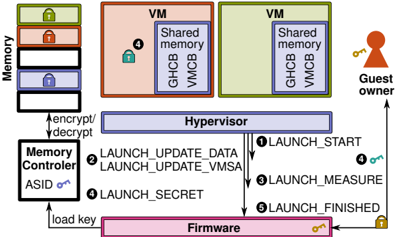
The image is a diagram illustrating a secure virtual machine (VM) launch process, emphasizing memory encryption and integrity. It depicts the interaction between various components, including memory, memory controller, hypervisor, firmware, and the guest owner. The diagram highlights the steps involved in launching a VM, focusing on security measures like encryption, measurement, and secret management.
### Components/Axes
* **Memory:** Stack of memory blocks, each potentially encrypted (indicated by lock icons). The stack has three blocks, colored green, red, and blue from top to bottom.
* **VM (Virtual Machine):** Two VM blocks, colored orange and green. Each contains "Shared memory", "GHCB", and "VMCB".
* **Guest Owner:** A figure representing the guest owner, holding a key.
* **Hypervisor:** A central component mediating access between VMs and the underlying hardware.
* **Memory Controller:** Responsible for encrypting/decrypting memory. It has an "ASID" (Address Space Identifier) and a key icon.
* **Firmware:** The lowest-level software, responsible for initializing the system. It also has a key icon.
* **Numbered Arrows:** Indicate the sequence of steps in the VM launch process.
### Detailed Analysis
1. **Memory:**
* The memory stack shows three blocks, each with a lock icon, suggesting encryption.
* The blocks are colored green (top), red (middle), and blue (bottom).
2. **VMs:**
* Two VMs are shown, one orange and one green.
* Each VM contains "Shared memory", "GHCB", and "VMCB".
* The orange VM has a blue lock icon.
3. **Hypervisor:**
* Positioned centrally, mediating access between VMs and hardware.
4. **Memory Controller:**
* Connected to the memory stack and the hypervisor.
* Handles encryption/decryption of memory.
* Has an "ASID" and a key icon.
5. **Firmware:**
* Located at the bottom of the diagram.
* Connected to the memory controller and the hypervisor.
* Has a key icon.
6. **Guest Owner:**
* Located on the right side of the diagram.
* Connected to the hypervisor.
* Holds a key.
7. **Launch Process Steps:**
* **① LAUNCH\_START:** Arrow from Hypervisor to Firmware.
* **② LAUNCH\_UPDATE\_DATA, LAUNCH\_UPDATE\_VMSA:** Arrow from Hypervisor to Firmware.
* **③ LAUNCH\_MEASURE:** Arrow from Hypervisor to Firmware.
* **④ LAUNCH\_SECRET:** Arrow from Hypervisor to Firmware. A blue key is associated with this step, also present in the orange VM.
* **⑤ LAUNCH\_FINISHED:** Arrow from Hypervisor to Firmware.
8. **Other Connections:**
* "encrypt/decrypt" arrow between Memory Controller and Memory.
* "load key" arrow between Firmware and Memory Controller.
* Arrow from Guest Owner to Hypervisor.
### Key Observations
* The diagram emphasizes security through encryption (lock icons) and controlled access (Hypervisor).
* The launch process involves multiple steps, each potentially involving security checks or updates.
* The Firmware plays a crucial role in the launch process, interacting with the Hypervisor and Memory Controller.
* The Guest Owner interacts with the Hypervisor, likely for VM management.
### Interpretation
The diagram illustrates a secure VM launch process, highlighting the importance of memory encryption, integrity checks, and controlled access. The Hypervisor acts as a central mediator, ensuring that the VM is launched securely. The Firmware plays a critical role in initializing the system and loading keys. The numbered steps indicate a sequence of actions that must be performed to ensure a secure launch. The presence of lock icons on memory blocks and VMs suggests that encryption is used to protect sensitive data. The "LAUNCH\_MEASURE" step indicates that the system measures the VM's state to ensure its integrity. The "LAUNCH\_SECRET" step suggests that secrets are securely managed during the launch process. The overall process aims to prevent unauthorized access to the VM and protect it from tampering.