## System Architecture Diagram: Secure Virtual Machine Launch Process
### Overview
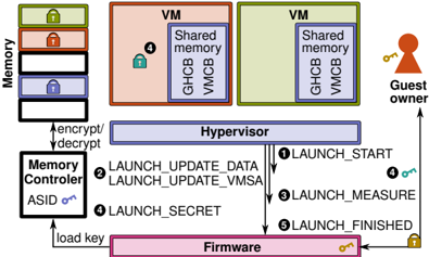
The diagram illustrates a secure virtual machine (VM) launch process involving memory encryption, hypervisor operations, firmware interactions, and guest owner authentication. Key components include memory regions, VMs with shared memory, a hypervisor, firmware, and a guest owner entity. Arrows represent data flow and process steps.
### Components/Axes
1. **Memory**:
- Stacked blocks with colored locks (green, red, blue, black) labeled "Memory."
- Arrows labeled "encrypt/decrypt" connect to the Memory Controller.
2. **VMs**:
- Two VM boxes (orange and green) labeled "VM" with "Shared memory" sub-boxes containing "GHCB" and "VM CB."
3. **Hypervisor**:
- Central purple box labeled "Hypervisor" with numbered steps:
1. LAUNCH_START
2. LAUNCH_UPDATE_DATA
3. LAUNCH_UPDATE_VMSA
4. LAUNCH_SECRET
5. LAUNCH_FINISHED
4. **Firmware**:
- Pink box labeled "Firmware" with a key icon.
5. **Guest Owner**:
- Red silhouette with a key icon, connected to Firmware via an arrow labeled "load key."
6. **Memory Controller**:
- Black box labeled "Memory Controller" with "ASID" and a key icon.
### Detailed Analysis
- **Memory**:
- Four memory regions with distinct locks (green, red, blue, black) suggest tiered security or access levels.
- Encryption/decryption arrows indicate dynamic memory protection.
- **VMs**:
- Shared memory regions (GHCB, VM CB) imply inter-VM communication or resource sharing.
- Orange and green colors may differentiate VM types or security domains.
- **Hypervisor**:
- Sequential steps (1–5) outline VM launch phases, including data updates, measurement, and secret handling.
- Step 3 ("LAUNCH_MEASURE") likely involves integrity checks.
- **Firmware**:
- Key icon suggests cryptographic operations or secure boot functionality.
- **Guest Owner**:
- Key icon implies ownership verification or authorization.
- **Memory Controller**:
- ASID (Address Space Identifier) and key icon indicate memory isolation and encryption key management.
### Key Observations
- **Sequential Process**: VM launch follows a strict workflow from start to finish, with hypervisor mediating security-critical steps.
- **Shared Memory Risks**: GHCB/VM CB in VMs could be attack vectors; hypervisor updates (steps 2–4) likely mitigate this.
- **Key Management**: Keys are central to encryption (Memory Controller), firmware, and guest owner authentication.
- **Color Coding**:
- Green (Memory), red/orange (VMs), purple (Hypervisor), pink (Firmware), black (Memory Controller) visually segregate components.
- No explicit legend, but colors align with component roles (e.g., red for "Guest Owner" matches the silhouette).
### Interpretation
This diagram represents a **secure enclave architecture** for VMs, emphasizing memory encryption, hypervisor-mediated security, and firmware/firmware-rooted trust. The Guest Owner’s key suggests a hardware-rooted identity (e.g., TPM or secure element) validating VM launches. The hypervisor’s role in updating data and measuring VM state aligns with attestation processes, ensuring VMs are launched in a trusted state. The Memory Controller’s ASID and key management highlight memory-level isolation, critical for preventing side-channel attacks. The shared memory in VMs (GHCB/VM CB) may enable secure inter-VM communication but requires hypervisor oversight to prevent leaks. The absence of explicit numerical data suggests this is a conceptual flow rather than a performance benchmark.