\n
## Diagram: Mechanism with Linkages
### Overview
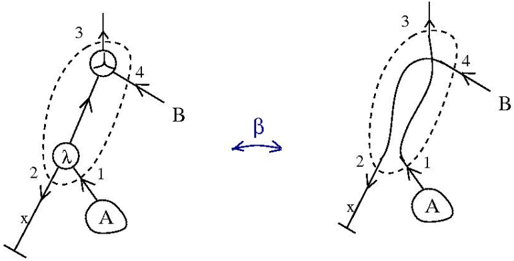
The image depicts a mechanical linkage system with two configurations, separated by a bidirectional arrow labeled "β". The system consists of a fixed base (labeled 'A'), a series of links, and a circular component with an applied force. The diagram illustrates how the system transforms between two states, likely representing different stages of motion or force application.
### Components/Axes
The diagram features the following components:
* **A:** Fixed base, positioned at the bottom-left of each configuration.
* **Links:** Four links are numbered 1, 2, 3, and 4.
* **λ (Lambda):** A circular node representing a joint or connection point.
* **B:** A point where a force is applied.
* **β:** Bidirectional arrow indicating a transformation or change in configuration.
* **Vertical Force:** An arrow pointing upwards, indicating an applied vertical force.
* **Dotted Lines:** Represent the range of motion or possible positions of the links.
There are no explicit axes in this diagram. The positioning of the components implies a spatial relationship.
### Detailed Analysis or Content Details
**Left Configuration:**
* Link 1 connects point A to the circular node λ.
* Link 2 connects λ to point 3.
* Link 3 extends vertically upwards, with the applied vertical force acting on it.
* Link 4 connects point 3 to point B.
* The circular node λ has an arrow indicating a rotational direction.
* The dotted lines show the possible range of motion for links 1 and 2.
**Right Configuration:**
* Link 1 connects point A to a point below λ.
* Link 2 connects to a point above λ.
* Link 3 extends vertically upwards, with the applied vertical force acting on it.
* Link 4 connects point 3 to point B.
* The dotted lines show the possible range of motion for links 1 and 2.
The arrow "β" is positioned horizontally between the two configurations, indicating a transformation.
### Key Observations
* The system appears to convert a vertical force into a horizontal displacement at point B.
* The configuration changes significantly with the transformation indicated by β.
* The circular node λ acts as a pivot point, changing its position and orientation between the two configurations.
* The dotted lines suggest a degree of freedom or range of motion for the links.
### Interpretation
This diagram likely represents a four-bar linkage mechanism. The transformation indicated by β suggests a change in the input or output of the mechanism. The vertical force applied at point 3 is likely the driving force, and the resulting motion at point B could be used to perform work. The diagram demonstrates how a linkage system can convert one type of motion (vertical force) into another (horizontal displacement). The change in configuration suggests a cyclical or reciprocating motion. The presence of λ indicates a rotational joint, and the dotted lines show the range of possible movements. The diagram is a simplified representation of a mechanical system, focusing on the key components and their relationships. It does not provide quantitative data, but rather illustrates the principle of operation.