## Memory Controller and DRAM Bank Diagram
### Overview
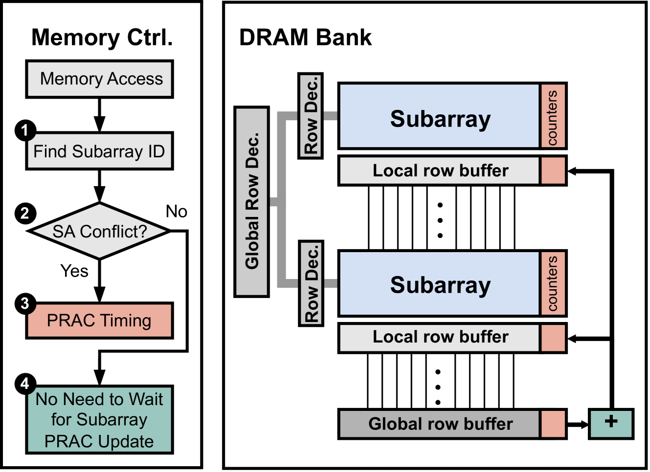
The image presents a diagram illustrating the interaction between a memory controller and a DRAM bank. It consists of two main sections: a flowchart representing the memory controller's operation and a schematic of the DRAM bank's architecture.
### Components/Axes
**Memory Controller (Left Side):**
* **Title:** Memory Ctrl.
* **Flowchart Steps:**
1. Memory Access (rectangular box)
2. Find Subarray ID (rectangular box, labeled "1")
3. SA Conflict? (diamond shape, labeled "2", with "Yes" and "No" branches)
4. PRAC Timing (rectangular box, labeled "3")
5. No Need to Wait for Subarray PRAC Update (rectangular box, labeled "4")
**DRAM Bank (Right Side):**
* **Title:** DRAM Bank
* **Components:**
* Global Row Dec. (vertical rectangular box, appears twice)
* Row Dec. (horizontal rectangular box, appears twice)
* Subarray (light blue rectangular box, appears twice)
* Local row buffer (gray rectangular box, appears twice)
* Global row buffer (gray rectangular box, appears once)
* counters (vertical text label, appears twice)
* "+" symbol (bottom-right)
### Detailed Analysis or ### Content Details
**Memory Controller Flowchart:**
1. **Memory Access:** The process begins with a memory access request.
2. **Find Subarray ID:** The memory controller identifies the specific subarray to be accessed.
3. **SA Conflict?:** A check is performed to determine if there is a subarray conflict.
* **Yes:** If there is a conflict, the process proceeds to PRAC Timing.
* **No:** If there is no conflict, the process loops back to the "PRAC Timing" step.
4. **PRAC Timing:** Timing considerations related to Precharge and Activate operations are handled.
5. **No Need to Wait for Subarray PRAC Update:** The final step indicates that no waiting is required for the subarray's PRAC update.
**DRAM Bank Architecture:**
* The DRAM bank consists of subarrays, local row buffers, and a global row buffer.
* Global Row Decoders and Row Decoders are used to select specific rows within the subarrays.
* Counters are associated with the subarrays.
* The "+" symbol at the bottom-right suggests an aggregation or combination of data from the global row buffer.
* Vertical lines connect the "Local row buffer" to the "Subarray" above it.
### Key Observations
* The flowchart illustrates the steps involved in accessing memory within the DRAM bank.
* The DRAM bank architecture shows a hierarchical structure with subarrays, local row buffers, and a global row buffer.
* The "SA Conflict?" check is a crucial step in determining whether timing adjustments are needed.
### Interpretation
The diagram provides a high-level overview of how a memory controller interacts with a DRAM bank. The memory controller's flowchart outlines the steps involved in accessing memory, including identifying the subarray, checking for conflicts, and handling timing considerations. The DRAM bank architecture shows the organization of memory cells into subarrays, buffers, and decoders. The interaction between the memory controller and the DRAM bank is essential for efficient and reliable memory access. The "SA Conflict?" step suggests a mechanism for handling potential contention or interference between memory access requests. The "+" symbol at the end suggests that the data from the global row buffer is aggregated or combined before being sent back to the memory controller.