## Heatmaps: Mean (Error: 2.90) and Standard Deviation (STD) of Conductance Relationships
### Overview
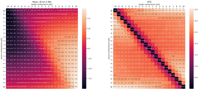
The image contains two side-by-side heatmaps comparing the relationship between source conductance (y-axis) and target conductance (x-axis). The left heatmap shows mean values with an error margin of ±2.90 µS, while the right heatmap displays standard deviation (STD) values. Both use a color gradient from dark blue (low values) to red (high values), with numerical annotations in each cell.
### Components/Axes
**Left Heatmap (Mean):**
- **X-axis (Target Conductance):** Labeled "target conductance (µS)" with values ranging from -10 to 10 in increments of 2 µS.
- **Y-axis (Source Conductance):** Labeled "source conductance (µS)" with values from -50 to 55 in increments of 5 µS.
- **Color Scale:** Ranges from -5.0 (dark blue) to 7.5 (red), labeled "Mean (Error: 2.90)".
- **Legend:** Positioned on the right, with a vertical gradient from dark blue to red.
**Right Heatmap (STD):**
- **X-axis (Target Conductance):** Same labels and range as the left heatmap.
- **Y-axis (Source Conductance):** Same labels and range as the left heatmap.
- **Color Scale:** Ranges from -3.5 (dark blue) to 3.5 (red), labeled "STD".
- **Legend:** Positioned on the right, with a vertical gradient from dark blue to red.
### Detailed Analysis
**Left Heatmap (Mean):**
- **Top-Left Cell (-10, -50):** -10.95 µS (dark blue).
- **Bottom-Right Cell (10, 55):** 7.50 µS (red).
- **Key Values:**
- -10.95, -9.79, -8.79, ..., 7.50 (scientific notation values in parentheses).
- Notable outliers: -15.00 µS (bottom-left quadrant) and 7.50 µS (bottom-right).
**Right Heatmap (STD):**
- **Top-Left Cell (-10, -50):** -3.50 µS (dark blue).
- **Bottom-Right Cell (10, 55):** 3.50 µS (red).
- **Key Values:**
- -3.50, -3.33, -3.11, ..., 3.50 (scientific notation values in parentheses).
- Notable outliers: -3.50 µS (top-left) and 3.50 µS (bottom-right).
### Key Observations
1. **Mean Heatmap Trends:**
- Gradual increase in mean values from left (negative) to right (positive) across the x-axis.
- Steeper gradient in the bottom-right quadrant (source conductance > 25 µS).
- Largest negative values (-15.00 µS) in the top-left quadrant (source conductance < -25 µS).
2. **STD Heatmap Trends:**
- Symmetrical distribution around the center (0 µS target conductance).
- Lowest variability (dark blue cells) in the top-left quadrant (-10 to 0 µS target conductance).
- Highest variability (red cells) in the bottom-right quadrant (target conductance > 25 µS).
3. **Color Consistency:**
- Dark blue cells in both heatmaps correspond to negative values (below -3.5 µS for STD, -5.0 µS for Mean).
- Red cells indicate positive values (above 3.5 µS for STD, 7.5 µS for Mean).
### Interpretation
The data suggests a **non-linear relationship** between source and target conductance:
- **Mean Error:** Higher source conductance correlates with larger positive errors, particularly in regions where target conductance exceeds 25 µS. This may indicate systematic bias in measurement accuracy at higher conductance levels.
- **Standard Deviation:** Lower variability in the top-left quadrant (source conductance < -25 µS) suggests more consistent measurements in low-conductance environments. The bottom-right quadrant shows higher variability, potentially due to measurement instability or environmental factors at high conductance levels.
- **Anomalies:** The -15.00 µS outlier in the Mean heatmap (bottom-left) and -3.50 µS in the STD heatmap (top-left) may represent edge cases or calibration thresholds.
These patterns highlight the importance of calibrating measurement systems for high-conductance environments and suggest that error margins are more predictable in low-conductance regimes.