## Diagram: System Architecture for Xylo HDK
### Overview
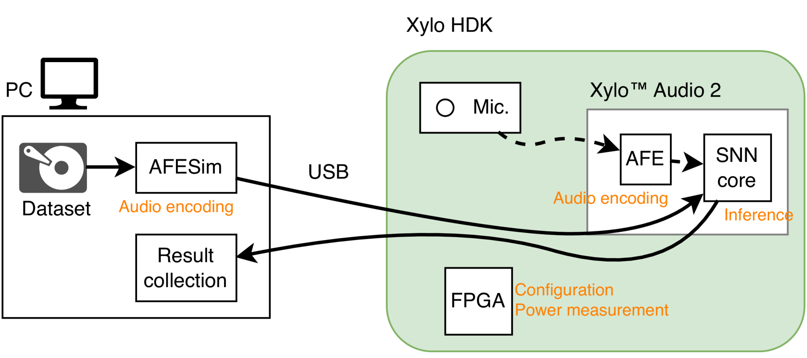
This diagram illustrates the system architecture and data flow for the Xylo Hardware Development Kit (HDK). It depicts a dual-mode operation environment: a simulation mode where a PC provides data to the Xylo hardware, and a live mode where a physical microphone provides input. The system is designed for testing and deploying Spiking Neural Network (SNN) applications.
### Components/Axes
The diagram is divided into two primary regions: the **PC (Left)** and the **Xylo HDK (Right)**.
**Left Region (PC):**
* **PC Icon:** Located at the top-left.
* **Dataset:** A box containing a hard drive icon and the label "Dataset".
* **AFESim:** A box labeled "AFESim" with the sub-label "Audio encoding" positioned directly below it.
* **Result collection:** A box labeled "Result collection" located below the AFESim box.
**Right Region (Xylo HDK):**
* **Container:** A large, rounded green rectangle labeled "Xylo HDK" at the top center.
* **Mic.:** A box containing a circle icon and the label "Mic." located in the top-left of the green container.
* **Xylo™ Audio 2:** A sub-box located in the top-right of the green container.
* **AFE:** A box inside the Xylo™ Audio 2 container with the sub-label "Audio encoding" below it.
* **SNN core:** A box inside the Xylo™ Audio 2 container with the sub-label "Inference" below it.
* **FPGA:** A box located in the bottom-left of the green container.
* **Configuration Power measurement:** A label positioned to the right of the FPGA box.
### Connections
* **USB:** A label placed above the line connecting the PC region to the Xylo HDK region.
* **Data Flow Lines:**
* Solid line from "Dataset" to "AFESim".
* Solid line from "AFESim" to "SNN core" (labeled "USB" at the connection point).
* Dashed line from "Mic." to "AFE".
* Solid line from "AFE" to "SNN core".
* Solid line from "SNN core" to "Result collection".
### Detailed Analysis
The diagram outlines two distinct workflows for the "SNN core":
1. **Simulation/Development Path:**
* Data originates from the "Dataset" on the PC.
* It passes through "AFESim" (Analog Front End Simulation), which performs "Audio encoding".
* The encoded data is sent via "USB" to the "SNN core" on the Xylo™ Audio 2 chip.
* The "SNN core" performs "Inference" and sends the output back to the "Result collection" block on the PC.
2. **Live Hardware Path:**
* Audio is captured by the "Mic." (Microphone).
* The signal is sent to the "AFE" (Analog Front End) on the Xylo™ Audio 2 chip.
* The AFE performs "Audio encoding" and passes the signal to the "SNN core".
* The "SNN core" performs "Inference".
**Supporting Components:**
* The **FPGA** is present within the Xylo HDK environment, likely serving as the controller for system configuration and power monitoring, as indicated by the label "Configuration Power measurement".
### Key Observations
* **Dual-Input Architecture:** The "SNN core" is the central processing hub, capable of receiving inputs from two distinct sources: the PC (via USB/AFESim) or the physical Microphone (via AFE).
* **Functional Parity:** The presence of "Audio encoding" labels under both "AFESim" and "AFE" suggests that the simulation environment is designed to mirror the hardware's analog front-end processing exactly.
* **Feedback Loop:** The system is closed-loop for the PC, as it both provides the input (Dataset) and collects the output (Result collection).
### Interpretation
This diagram represents a typical "Hardware-in-the-loop" (HIL) or development environment for neuromorphic computing.
* **Why it matters:** By providing an "AFESim" (Simulation) path, developers can validate their SNN models against pre-recorded datasets without needing to physically interact with the microphone or the Xylo hardware in real-time. This is crucial for debugging and training.
* **Peircean Investigative View:** The "Xylo™ Audio 2" is clearly the System-on-Chip (SoC) or primary processing unit. The separation of "AFE" and "SNN core" suggests a modular design where the analog signal processing is distinct from the neural network inference. The inclusion of the FPGA for "Configuration Power measurement" indicates that this is a development board (HDK) intended for power-sensitive edge AI applications, where monitoring energy consumption is as important as the inference accuracy.