## System Diagram: Xylo HDK Audio Processing Pipeline
### Overview
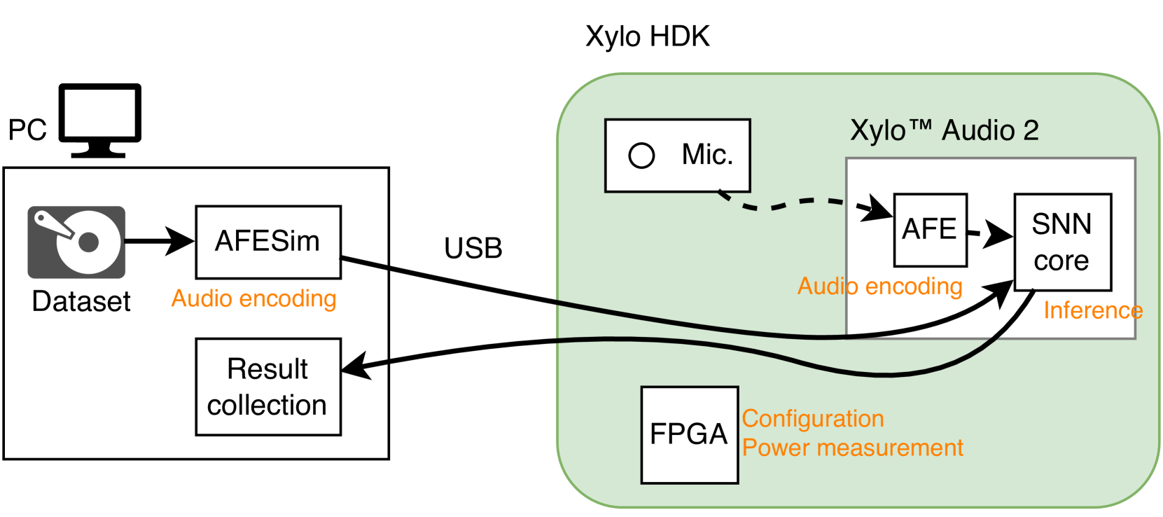
This image is a technical block diagram illustrating the data flow and components of an audio processing system. The system consists of two primary hardware/software environments: a host PC and a "Xylo HDK" (Hardware Development Kit). The diagram shows how an audio dataset is processed, sent to specialized hardware for inference, and how results are returned.
### Components/Axes
The diagram is divided into two main spatial regions:
1. **Left Region (Host PC):**
* **Icon:** A computer monitor labeled **"PC"**.
* **Main Block:** A large rectangle representing the PC's software environment.
* **Internal Components:**
* **"Dataset"**: Represented by an icon of a CD/DVD.
* **"AFESim"**: A processing block. An arrow points from "Dataset" to "AFESim".
* **"Result collection"**: A block that receives data.
* **Annotations:** The text **"Audio encoding"** in orange is placed below the "AFESim" block.
2. **Right Region (Xylo HDK):**
* **Main Container:** A large, light-green rounded rectangle labeled **"Xylo HDK"** at the top center.
* **Internal Components:**
* **"Mic."**: A block with a circle icon, representing a microphone input.
* **"Xylo™ Audio 2"**: A white sub-container within the HDK.
* **"AFE"**: A block inside "Xylo™ Audio 2".
* **"SNN core"**: A block inside "Xylo™ Audio 2", to the right of "AFE".
* **"FPGA"**: A separate block at the bottom of the HDK container.
* **Annotations:**
* **"Audio encoding"** in orange is placed below the "AFE" block.
* **"Inference"** in orange is placed below the "SNN core" block.
* **"Configuration"** and **"Power measurement"** in orange are placed to the right of the "FPGA" block.
3. **Connections & Data Flow:**
* A solid black arrow labeled **"USB"** connects the "AFESim" block (PC) to the "SNN core" block (Xylo HDK).
* A dashed black arrow connects the "Mic." block to the "AFE" block.
* A solid black arrow connects the "AFE" block to the "SNN core" block.
* A solid black arrow returns from the "SNN core" block (Xylo HDK) to the "Result collection" block (PC).
### Detailed Analysis
The diagram explicitly maps a functional pipeline:
1. **Source:** An audio **"Dataset"** is the starting point on the PC.
2. **Pre-processing/Simulation:** The dataset is fed into **"AFESim"** (likely Audio Front-End Simulator). The orange label **"Audio encoding"** indicates this block's function.
3. **Hardware Transfer:** The processed audio data is sent via a **"USB"** connection to the external hardware (Xylo HDK).
4. **Hardware Processing (Xylo HDK):**
* The **"Mic."** provides a live audio input path (dashed line) to the **"AFE"** (Audio Front-End) hardware block.
* The **"AFE"** block, also annotated with **"Audio encoding"**, processes the audio (either from the mic or the USB stream) and sends it to the **"SNN core"**.
* The **"SNN core"** (Spiking Neural Network core) performs the **"Inference"** task.
* The **"FPGA"** (Field-Programmable Gate Array) is shown as a separate component responsible for **"Configuration"** and **"Power measurement"** of the system.
5. **Result Return:** The output from the **"SNN core"** is sent back across the USB connection to the **"Result collection"** module on the PC.
### Key Observations
* **Dual Audio Paths:** The system supports two audio input paths: a simulated path from a dataset (via AFESim) and a live path from a microphone.
* **Functional Annotation:** Orange text is used consistently to label the *function* of components (Audio encoding, Inference, Configuration, Power measurement), while black text labels the *component names* (AFESim, AFE, SNN core, FPGA).
* **Central Role of SNN Core:** The "SNN core" is the central processing node, receiving data from both the USB (simulated dataset) and the AFE (live mic), and sending results back to the PC.
* **Hardware Abstraction:** The "Xylo™ Audio 2" is presented as a distinct module within the larger "Xylo HDK" development board, which also includes the FPGA for support functions.
### Interpretation
This diagram depicts a development and testing setup for a neuromorphic audio processing chip (the Xylo™ Audio 2 with its SNN core). The setup allows engineers to:
1. **Benchmark and Validate:** Use a known **"Dataset"** via the **"AFESim"** to test the SNN core's inference accuracy in a controlled, repeatable manner.
2. **Develop for Real-World Use:** Incorporate a live **"Mic."** input for real-time audio processing applications.
3. **Monitor and Configure:** Use the **"FPGA"** to configure the hardware and measure its power consumption, which is critical for evaluating efficiency in edge computing scenarios.
The flow suggests a closed-loop development cycle: data is sent to the hardware, processed by the neuromorphic core, and results are collected on the host PC for analysis. The presence of both simulation and live input paths indicates this HDK is designed for comprehensive algorithm development and hardware co-design, bridging the gap between software simulation and physical deployment.