## Processor Architecture Diagram: In-order Frontend, Out-of-order Execution, and In-order Retire
### Overview
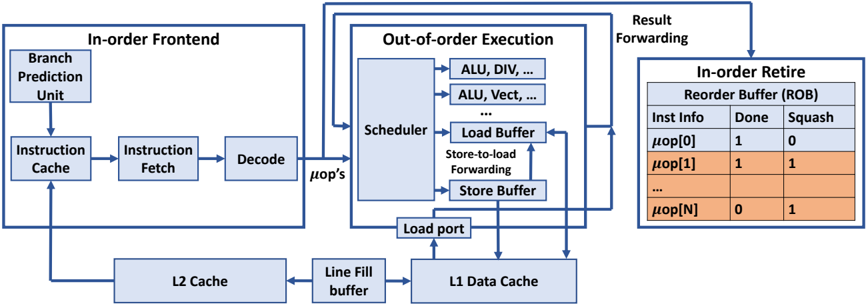
The image is a block diagram illustrating the architecture of a processor, highlighting the flow of instructions through different stages: In-order Frontend, Out-of-order Execution, and In-order Retire. It shows the components within each stage and the connections between them.
### Components/Axes
* **In-order Frontend:** This section includes the initial stages of instruction processing.
* Branch Prediction Unit
* Instruction Cache
* Instruction Fetch
* Decode
* **Out-of-order Execution:** This section shows the components involved in executing instructions out of order.
* Scheduler
* ALU, DIV, ...
* ALU, Vect, ...
* Load Buffer
* Store-to-load Forwarding
* Store Buffer
* Load port
* **In-order Retire:** This section shows the final stage where instructions are retired in order.
* Reorder Buffer (ROB)
* Columns: Inst Info, Done, Squash
* Rows: μop[0], μop[1], ..., μop[N]
* **Caches and Buffers:**
* L2 Cache
* Line Fill buffer
* L1 Data Cache
* **Arrows:** Indicate the flow of data and control signals between the components.
### Detailed Analysis or ### Content Details
**In-order Frontend:**
* The Branch Prediction Unit feeds into the Instruction Cache.
* The Instruction Cache feeds into the Instruction Fetch.
* The Instruction Fetch feeds into the Decode unit.
* The Decode unit outputs μop's (micro-operations) to the Scheduler in the Out-of-order Execution block.
* The L2 Cache feeds into the Instruction Cache.
**Out-of-order Execution:**
* The Scheduler is connected to multiple Arithmetic Logic Units (ALUs), including those for division (DIV) and vector operations (Vect).
* The Scheduler is also connected to the Load Buffer and Store Buffer.
* Store-to-load Forwarding is indicated between the Load Buffer and Store Buffer.
* The Load port connects the Load Buffer to the L1 Data Cache.
* Result Forwarding connects the Out-of-order Execution block to the In-order Retire block.
**In-order Retire:**
* The Reorder Buffer (ROB) contains information about instructions, including whether they are "Done" and whether they are "Squashed".
* The table shows the following data:
* μop[0]: Done = 1, Squash = 0
* μop[1]: Done = 1, Squash = 1
* μop[N]: Done = 0, Squash = 1
**Caches and Buffers:**
* The L2 Cache feeds into the Line Fill buffer.
* The Line Fill buffer feeds into the L1 Data Cache.
* The L1 Data Cache feeds into the Load port.
### Key Observations
* The diagram illustrates a common processor architecture with in-order instruction fetching and decoding, followed by out-of-order execution and in-order retirement.
* The Reorder Buffer (ROB) plays a crucial role in ensuring that instructions are retired in the correct order, even though they may have been executed out of order.
* The "Done" and "Squash" flags in the ROB indicate the status of each micro-operation.
### Interpretation
The diagram provides a high-level overview of a processor's architecture, emphasizing the key stages of instruction processing. The separation of the frontend (in-order), execution (out-of-order), and retirement (in-order) stages allows for efficient instruction processing by overlapping the execution of multiple instructions. The Reorder Buffer (ROB) is essential for maintaining program order and handling exceptions or mispredicted branches. The "Squash" flag indicates that an instruction needs to be discarded, likely due to a branch misprediction or an exception. The data in the ROB table shows examples of instructions that are done and not squashed (μop[0]), done and squashed (μop[1]), and not done but squashed (μop[N]).