\n
## Diagram: Processor Pipeline Architecture
### Overview
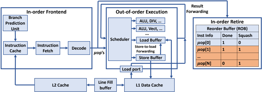
The image depicts a simplified block diagram of a processor pipeline, illustrating the flow of instructions from the front-end through out-of-order execution to retirement. It highlights key components like the instruction cache, decode stage, scheduler, load/store buffers, and reorder buffer (ROB). The diagram shows data flow with arrows and includes a small table representing the state of micro-operations (μops) within the ROB.
### Components/Axes
The diagram is segmented into three main areas:
1. **In-order Frontend:** Contains the Branch Prediction Unit, Instruction Cache, Instruction Fetch, and Decode stages.
2. **Out-of-order Execution:** Includes the Scheduler, Load Buffer, Store-to-load Forwarding, Store Buffer, ALU (Arithmetic Logic Unit), and Load Port.
3. **In-order Retire Reorder Buffer (ROB):** Displays the status of micro-operations with columns for "Inst Info", "Done", and "Squash".
There are also two cache levels shown: L2 Cache and L1 Data Cache, connected via a "Line Fill buffer".
### Detailed Analysis or Content Details
**In-order Frontend:**
* **Branch Prediction Unit:** Feeds into the Instruction Cache.
* **Instruction Cache:** Outputs to Instruction Fetch.
* **Instruction Fetch:** Passes instructions to Decode.
* **Decode:** Outputs μops (micro-operations) to the Out-of-order Execution stage.
**Out-of-order Execution:**
* **Scheduler:** Receives μops from Decode and distributes them to execution units (ALU, DIV, ALU Vect).
* **ALU, DIV, ALU Vect:** Represent various execution units.
* **Load Buffer:** Handles load operations.
* **Store-to-load Forwarding:** A mechanism for forwarding data from store operations to load operations.
* **Store Buffer:** Handles store operations.
* **Load Port:** Connects to the L1 Data Cache.
**L1 & L2 Cache:**
* **L2 Cache:** Connected to the Line Fill buffer.
* **Line Fill buffer:** Connects to the L1 Data Cache.
* **L1 Data Cache:** Receives data from the Load Port.
**In-order Retire Reorder Buffer (ROB):**
The table within the ROB shows the status of several μops. The table has three columns:
* **Inst Info:** Represents the micro-operation identifier (μop[0] to μop[N]).
* **Done:** Indicates whether the μop has completed execution (1 = yes, 0 = no).
* **Squash:** Indicates whether the μop needs to be squashed (1 = yes, 0 = no).
The table shows the following data:
* μop[0]: Done = 1, Squash = 0
* μop[1]: Done = 1, Squash = 1
* ... (Ellipsis indicates more rows)
* μop[N]: Done = 0, Squash = 1
**Data Flow:**
Instructions flow from left to right. The In-order Frontend feeds μops to the Out-of-order Execution stage. Results are forwarded back to the In-order Retire Reorder Buffer for final retirement. Cache interactions are shown with data flowing between L2 Cache, L1 Data Cache, and the Load Port.
### Key Observations
* The pipeline is divided into distinct stages, allowing for parallel processing.
* The Out-of-order Execution stage enables the processor to execute instructions in a non-sequential order to improve performance.
* The ROB ensures that instructions are retired in the original program order, even if they are executed out of order.
* The "Squash" column in the ROB table indicates that some μops have been invalidated, likely due to branch mispredictions or data dependencies.
* The ellipsis (...) in the ROB table suggests that the ROB can hold a larger number of μops than are explicitly shown.
### Interpretation
This diagram illustrates a common architecture for modern processors. The separation of the pipeline into in-order and out-of-order stages allows for a balance between simplicity and performance. The out-of-order execution unit attempts to maximize instruction-level parallelism, while the in-order retirement unit maintains program correctness. The ROB is crucial for handling exceptions and ensuring that the processor state remains consistent. The presence of the "Squash" column in the ROB table suggests that the processor is actively handling branch mispredictions or other events that require the invalidation of previously executed instructions. The cache hierarchy (L1 and L2) is essential for reducing memory access latency and improving overall performance. The diagram provides a high-level overview of the processor's internal workings and highlights the key components and data flow paths. The diagram does not provide any quantitative data, such as pipeline depth or cache sizes, but it effectively conveys the fundamental principles of a modern processor pipeline.