## Diagram: Kernel Data Flow Between Sequential Processing Steps
### Overview
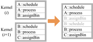
The diagram illustrates the flow of data between two sequential computational kernels (Kernel (i) and Kernel (i+1)) in a parallel processing system. It shows three data entries per kernel, with an orange arrow indicating the directional flow from Kernel (i) to Kernel (i+1). The structure suggests a pipeline or staged computation where outputs from one kernel feed into the next.
### Components/Axes
- **Kernel (i)**:
- **A::schedule**: Topmost entry in Kernel (i).
- **A::process**: Middle entry in Kernel (i).
- **B::assignBin**: Bottom entry in Kernel (i).
- **Kernel (i+1)**:
- **B::schedule**: Topmost entry in Kernel (i+1).
- **B::process**: Middle entry in Kernel (i+1).
- **C::assignBin**: Bottom entry in Kernel (i+1).
- **Flow Indicator**: An orange arrow connects Kernel (i) to Kernel (i+1), positioned centrally between the two blocks.
### Detailed Analysis
- **Kernel (i)** contains three labeled components:
1. **A::schedule**: Likely represents scheduling operations for task A.
2. **A::process**: Represents processing logic for task A.
3. **B::assignBin**: Indicates bin assignment operations for task B.
- **Kernel (i+1)** inherits and modifies the flow:
1. **B::schedule**: Scheduling for task B (inherited from Kernel (i)).
2. **B::process**: Processing for task B (inherited and continued).
3. **C::assignBin**: Introduces a new bin assignment operation for task C, suggesting expanded functionality or additional data partitioning.
- The orange arrow emphasizes the sequential dependency: outputs from Kernel (i) (e.g., B::assignBin) are prerequisites for Kernel (i+1) (e.g., B::schedule).
### Key Observations
1. **Sequential Dependency**: Kernel (i+1) relies on the completion of Kernel (i), particularly the B::assignBin operation.
2. **Component Expansion**: The introduction of C::assignBin in Kernel (i+1) implies incremental complexity or scalability in the processing pipeline.
3. **Label Consistency**: The use of "::" notation suggests a namespace or object-oriented structure (e.g., class::method).
### Interpretation
This diagram likely represents a parallel computing workflow, such as in GPU programming (e.g., CUDA) or distributed systems. The progression from Kernel (i) to Kernel (i+1) demonstrates:
- **Pipeline Optimization**: Tasks are split into stages to maximize throughput.
- **Data Partitioning**: The "assignBin" operations suggest data is distributed across bins (e.g., for parallel reduction or sorting).
- **Modular Design**: Each kernel encapsulates specific responsibilities (scheduling, processing, bin management), promoting reusability and maintainability.
The absence of numerical values or trends indicates this is a conceptual flow diagram rather than a performance metric. The orange arrow’s central placement underscores the critical role of inter-kernel communication in maintaining process continuity.