## Diagram: Hardware Architecture for LUT-Based Accumulation System
### Overview
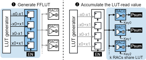
The diagram illustrates a two-stage hardware architecture for generating and accumulating Look-Up Table (LUT) read values. It is divided into two primary functional blocks:
1. **Generate FFLUT** (left side)
2. **Accumulate the LUT-read value** (right side)
The system uses a combination of LUT generators, RAC (Register-Accumulate) blocks, and Psum (Partial Sum) units to process input signals (`x0`, `x1`) and keys (`Key0`, `Key1`, `Key2`).
---
### Components/Axes
#### Left Diagram: Generate FFLUT
- **LUT Generator**:
- Inputs: `x0`, `x1`
- Outputs: Four intermediate values:
- `-x0-x1`
- `-x0+x1`
- `x0-x1`
- `x0+x1`
- Position: Top-left quadrant, connected to RAC blocks via arrows.
- **RAC Blocks**:
- **RAC0**, **RAC1**, **RAC2**:
- Each receives one of the four LUT generator outputs.
- Position: Center-left, vertically stacked.
- Connected to an **EN** (Enable) block at the bottom.
#### Right Diagram: Accumulate the LUT-read value
- **LUT Generator**:
- Same four outputs as the left diagram (`-x0-x1`, `-x0+x1`, `x0-x1`, `x0+x1`).
- Position: Top-left quadrant, connected to RAC blocks.
- **RAC Blocks**:
- **RAC0**, **RAC1**, **RAC2**:
- Share the same LUT generator outputs.
- Position: Center-left, vertically stacked.
- Connected to **Psum** blocks via arrows labeled `Key0`, `Key1`, `Key2`.
- **Psum Blocks**:
- **Psum0**, **Psum1**, **Psum2**:
- Receive inputs from RAC blocks and keys.
- Position: Right side, vertically stacked.
- **EN Block**:
- Position: Bottom-center, connected to the LUT generator.
---
### Detailed Analysis
#### Left Diagram: Generate FFLUT
1. The LUT generator produces four intermediate values by combining `x0` and `x1` with arithmetic operations.
2. These values are routed to three RAC blocks (RAC0, RAC1, RAC2).
3. The **EN** block likely controls the enable signal for the RAC blocks.
#### Right Diagram: Accumulate the LUT-read value
1. The LUT generator outputs are reused to feed the same RAC blocks.
2. Each RAC block is connected to a Psum block via a unique key (`Key0`, `Key1`, `Key2`).
3. The Psum blocks aggregate the RAC outputs, suggesting a multi-stage accumulation process.
---
### Key Observations
1. **Shared LUT**: The right diagram explicitly states that `k RACs share LUT`, indicating resource reuse for efficiency.
2. **Key-Driven Accumulation**: The Psum blocks use distinct keys, implying conditional or weighted accumulation.
3. **EN Block Role**: The Enable block acts as a control point for both diagrams, suggesting synchronization between generation and accumulation phases.
---
### Interpretation
This architecture appears to implement a **hardware-accelerated LUT-based computation system**, likely for applications requiring rapid arithmetic operations (e.g., digital signal processing, cryptography).
- **Stage 1 (Generate FFLUT)**: Computes intermediate values from input signals, stored in RAC blocks.
- **Stage 2 (Accumulate)**: Reuses the LUT to process the same intermediate values but applies key-specific logic via Psum blocks.
The shared LUT and key-driven accumulation suggest optimization for parallelism and reduced hardware footprint. The EN block ensures temporal coordination between the two stages.
**Notable Design Choices**:
- Reuse of LUT outputs across RAC blocks minimizes redundancy.
- Key-based Psum blocks enable flexible accumulation logic without additional LUT entries.
- The EN block centralizes control, simplifying synchronization.
This design prioritizes efficiency and scalability, critical for high-performance computing systems.