## Quantum Key Distribution Diagram
### Overview
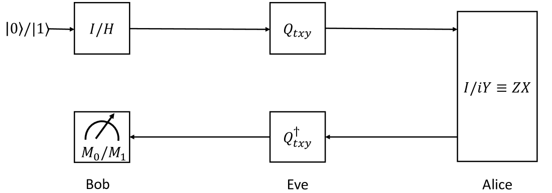
The image is a block diagram illustrating a quantum key distribution (QKD) protocol, likely BB84 or a variant. It shows the flow of quantum states between Alice, Bob, and Eve, including encoding, transmission, and measurement steps.
### Components/Axes
* **Nodes:**
* Alice: The sender of the quantum states.
* Bob: The intended receiver of the quantum states.
* Eve: An eavesdropper attempting to intercept the quantum states.
* **Quantum State Initialization:** The process begins with the input "|0>/|1>".
* **Encoding (Alice):** Alice encodes the quantum states using "I/iY = ZX".
* **Quantum Channel:** The quantum states are transmitted through a channel, potentially intercepted by Eve.
* **Eve's Interception:** Eve intercepts the quantum states using "Q†xy".
* **Decoding (Bob):** Bob measures the quantum states using "M0/M1".
* **Blocks:**
* I/II: Initial state preparation.
* Q\_txy: Quantum operation by Alice.
* Q†\_txy: Quantum operation by Eve.
* M0/M1: Measurement by Bob.
* I/iY = ZX: Alice's encoding operation.
### Detailed Analysis or Content Details
1. **Initial State:** The process starts with a quantum state represented as "|0>/|1>". This indicates that the initial state can be either |0> or |1>.
2. **Alice's Encoding:** Alice applies an operation denoted as "I/II" to the initial state. This could represent a choice of basis for encoding the quantum information. The encoded state is then transformed by "Q\_txy".
3. **Quantum Channel:** The encoded quantum state is sent through a quantum channel to Bob.
4. **Eve's Interception:** Eve intercepts the quantum state and applies a transformation denoted as "Q†\_txy". This represents Eve's eavesdropping attempt.
5. **Bob's Measurement:** Bob receives the (potentially altered) quantum state and performs a measurement using "M0/M1". This represents Bob's attempt to decode the quantum information.
6. **Alice's Operation Details:** The block labeled "I/iY = ZX" suggests that Alice's encoding involves a combination of Identity (I), Pauli-Y (iY), Pauli-Z (Z), and Pauli-X (X) operations.
### Key Observations
* The diagram illustrates a typical QKD scenario where Alice and Bob attempt to establish a secure key while Eve tries to intercept the communication.
* The presence of "Q\_txy" and "Q†\_txy" indicates that Eve's interception is modeled as a quantum operation.
* The measurement "M0/M1" suggests that Bob is performing a projective measurement on the received quantum state.
### Interpretation
The diagram represents a simplified model of a quantum key distribution protocol. The key idea is that any attempt by Eve to intercept the quantum states will introduce detectable disturbances, allowing Alice and Bob to detect the eavesdropping and discard the compromised key. The specific operations "I/iY = ZX", "Q\_txy", and "Q†\_txy" would need further context to fully understand the protocol being depicted. The diagram highlights the fundamental steps of QKD: state preparation, encoding, transmission, interception (potential), and measurement.