TECHNICAL ASSET FINGERPRINT
0bc5735e2ca452718684ad7d
Click to view fullscreen
Press ESC or click to close
FOUND IN PAPERS
EXPERT: healer-alpha-free VERSION 1
RUNTIME: free/openrouter/healer-alpha
INTEL_VERIFIED
## Diagram: Signed Binary Multiplication Methods
### Overview
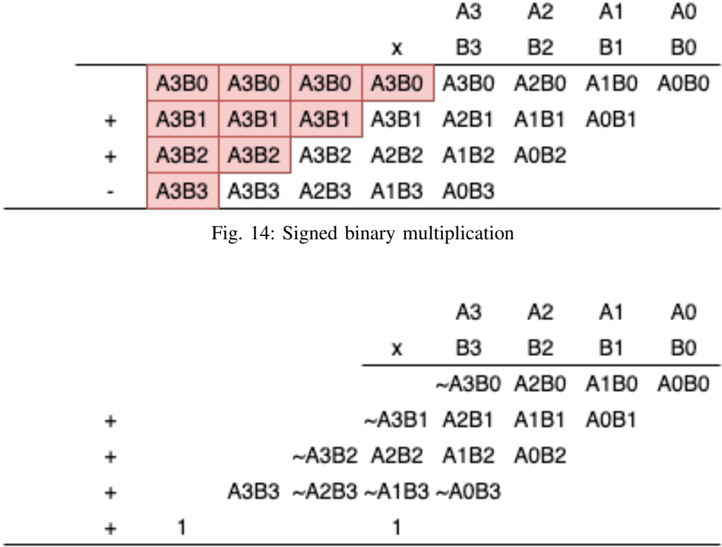
The image displays two technical diagrams illustrating different methods for performing signed binary multiplication using 4-bit numbers. The top diagram (labeled Fig. 14) shows a standard partial product accumulation method. The bottom diagram shows an alternative method that incorporates sign extension (indicated by tildes `~`) and the addition of correction terms (the `1`s at the bottom). Both diagrams use the same operand structure: a 4-bit multiplicand `A` (bits A3, A2, A1, A0) and a 4-bit multiplier `B` (bits B3, B2, B1, B0).
### Components/Axes
**Common Structure (Both Diagrams):**
* **Operands:** Two 4-bit binary numbers are multiplied.
* Multiplicand: `A3 A2 A1 A0` (where A3 is the most significant bit, likely the sign bit).
* Multiplier: `B3 B2 B1 B0` (where B3 is the most significant bit, likely the sign bit).
* **Operation:** Multiplication (`x` symbol).
* **Partial Products:** The core of the diagram shows the generation and summation of partial products. Each partial product is a 1-bit AND operation between a bit from `A` and a bit from `B` (e.g., `A3B0`).
**Top Diagram (Fig. 14: Signed binary multiplication):**
* **Layout:** A grid-like table.
* **Rows:** Four rows of partial products, each shifted left relative to the previous one, corresponding to the weight of the multiplier bit (B0, B1, B2, B3).
* **Columns:** Represent bit positions in the accumulating result.
* **Highlighting:** The four leftmost partial products in the first three rows (`A3B0`, `A3B1`, `A3B2`) and the entire fourth row (`A3B3`, `A3B3`, `A3B3`, `A1B3`) are highlighted with a light red background. This likely indicates sign extension or special handling for the sign bit (A3).
* **Operators:** `+` signs are shown to the left of the second, third, and fourth rows, indicating summation. A `-` sign is shown to the left of the fourth row, which is unusual and may indicate a subtraction or a specific encoding for signed multiplication (e.g., Booth's algorithm).
**Bottom Diagram:**
* **Layout:** Similar grid structure to the top diagram.
* **Key Difference - Notation:** Uses tildes (`~`) before some partial product terms (e.g., `~A3B0`, `~A2B3`, `~A1B3`, `~A0B3`). The tilde typically denotes a bitwise NOT operation or indicates that the term is subtracted rather than added in some signed multiplication schemes.
* **Additional Terms:** Two separate `1` values are added at the very bottom, aligned under the columns for what would be bit positions 4 and 7 (counting from the right, starting at 0). This is characteristic of algorithms that convert multiplication of signed numbers into operations on their magnitudes with correction factors.
### Detailed Analysis
**Top Diagram (Fig. 14) - Row-by-Row Breakdown:**
1. **Row 1 (Multiplier Bit B0):** `A3B0 A3B0 A3B0 A3B0 A3B0 A2B0 A1B0 A0B0`
* *Trend/Pattern:* The term `A3B0` is repeated five times across the most significant positions. This is a clear sign extension of the product of the sign bit of A with the LSB of B.
2. **Row 2 (Multiplier Bit B1):** `+ A3B1 A3B1 A3B1 A3B1 A2B1 A1B1 A0B1`
* *Trend/Pattern:* Shifted one position left. Again, `A3B1` is repeated four times for sign extension.
3. **Row 3 (Multiplier Bit B2):** `+ A3B2 A3B2 A3B2 A2B2 A1B2 A0B2`
* *Trend/Pattern:* Shifted left. `A3B2` is repeated three times.
4. **Row 4 (Multiplier Bit B3 - Sign Bit):** `- A3B3 A3B3 A3B3 A1B3 A0B3`
* *Trend/Pattern:* Shifted left. `A3B3` is repeated three times. The leading `-` sign is a critical detail, suggesting this row is subtracted, which is a key step in some signed multiplication algorithms to correct for the negative weight of the sign bit.
**Bottom Diagram - Row-by-Row Breakdown:**
1. **Row 1 (B0):** `~A3B0 A2B0 A1B0 A0B0`
* *Trend/Pattern:* Only the term involving the sign bit A3 is negated (`~A3B0`). No repetition/sign extension is shown in this notation.
2. **Row 2 (B1):** `+ ~A3B1 A2B1 A1B1 A0B1`
* *Trend/Pattern:* Shifted left. `~A3B1` is negated.
3. **Row 3 (B2):** `+ ~A3B2 A2B2 A1B2 A0B2`
* *Trend/Pattern:* Shifted left. `~A3B2` is negated.
4. **Row 4 (B3):** `+ A3B3 ~A2B3 ~A1B3 ~A0B3`
* *Trend/Pattern:* Shifted left. Here, the pattern inverts: the term `A3B3` is positive, while all other terms from the multiplicand (`A2B3`, `A1B3`, `A0B3`) are negated.
5. **Correction Terms:** `+ 1` (aligned under column ~A3B2/A2B3) and `+ 1` (aligned under column ~A3B0/A2B1/A1B2/A0B3).
* *Trend/Pattern:* These two `1`s are added to the final sum, which is a hallmark of two's complement arithmetic correction.
### Key Observations
1. **Sign Bit Handling:** Both diagrams explicitly isolate and treat the most significant bits (A3 and B3) differently from the lower-order bits, which is the fundamental challenge in signed binary multiplication.
2. **Algorithmic Difference:** The top diagram (Fig. 14) uses a method involving sign extension (repetition of `A3Bx` terms) and a subtraction for the final row. The bottom diagram uses a method involving negation (tildes) of specific partial products and the addition of correction constants (`1`s).
3. **Spatial Layout:** The partial products are arranged in a classic, shifted multiplication tableau. The correction `1`s in the bottom diagram are placed in specific columns, indicating they affect particular bit positions in the final sum.
4. **Highlighting:** The red highlighting in Fig. 14 draws attention to the terms involving the sign bit A3, emphasizing their special role in the calculation.
### Interpretation
These diagrams are instructional tools explaining the hardware-level or algorithmic steps for multiplying signed binary numbers (likely in two's complement representation).
* **What the data suggests:** The diagrams demonstrate that signed multiplication is not as straightforward as unsigned multiplication. Simply ANDing all bit pairs and summing them would yield an incorrect result for negative numbers because the sign bit (MSB) has a negative weight (-2^n) in two's complement, while all other bits have positive weights.
* **How elements relate:** Each row corresponds to the partial product formed by multiplying the entire multiplicand `A` by a single bit of the multiplier `B`. The leftward shift of each subsequent row accounts for the binary weight (2^0, 2^1, 2^2, 2^3) of the multiplier bits. The special treatment of the `A3Bx` terms (via sign extension/subtraction in Fig. 14, or via negation in the bottom diagram) corrects for the negative weight of the A3 bit.
* **Notable Anomalies/Insights:**
* The `-` sign in Fig. 14 is the most striking visual cue. It indicates that the contribution of the partial products involving the multiplier's sign bit (B3) is subtracted, not added. This aligns with algorithms that treat the sign bit as having a value of -2^3 instead of +2^3.
* The bottom diagram's structure, with its negated terms and added `1`s, strongly suggests it is illustrating **Booth's Algorithm** or a similar radix-2 signed multiplication scheme. Booth's algorithm recodes the multiplier to reduce the number of partial products and handles signs through addition and subtraction of shifted versions of the multiplicand. The two `1`s are the correction needed when the recoding results in a net subtraction.
* The two diagrams likely represent two different but equivalent ways to conceptualize the same mathematical operation: multiplying two signed 4-bit numbers to produce a signed 8-bit result. The top one is more visual (showing all partial products), while the bottom one is more algorithmic (showing the operations to be performed).
DECODING INTELLIGENCE...