## State Transition Diagram: Future and Present States of W and H
### Overview
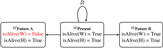
The image displays a state transition diagram with three rectangular nodes representing different states, connected by directional arrows indicating possible transitions. The diagram models the logical states of two entities, "W" and "H," across a present moment and two possible future scenarios.
### Components/Axes
The diagram consists of three primary components (states) arranged horizontally:
1. **Left Node (wFuture A):** A rectangle containing the text:
* `wFuture A`
* `isAlive(W) = False` (This line is colored red)
* `isAlive(H) = True`
2. **Center Node (wPresent):** A rectangle containing the text:
* `wPresent`
* `isAlive(W) = True`
* `isAlive(H) = True`
3. **Right Node (wFuture B):** A rectangle containing the text:
* `wFuture B`
* `isAlive(W) = True`
* `isAlive(H) = True`
**Transitions (Arrows):**
* A horizontal arrow points from the **right side of the `wPresent` node** to the **left side of the `wFuture A` node**.
* A horizontal arrow points from the **right side of the `wPresent` node** to the **left side of the `wFuture B` node**.
* A curved arrow originates from the **top of the `wPresent` node**, loops upward and to the right, and points back to the **top of the `wPresent` node**. This self-loop is labeled with the letter **`R`**.
### Detailed Analysis
The diagram defines three distinct states based on the boolean values of `isAlive(W)` and `isAlive(H)`:
* **State `wPresent`:** Both W and H are alive (`True`).
* **State `wFuture A`:** W is not alive (`False`, highlighted in red), while H is alive (`True`).
* **State `wFuture B`:** Both W and H are alive (`True`), identical to the `wPresent` state in terms of the `isAlive` predicates.
**Transitions and Flow:**
1. From the central `wPresent` state, the system can transition to either `wFuture A` or `wFuture B`.
2. The transition to `wFuture A` represents a future where W's status changes from alive to not alive.
3. The transition to `wFuture B` represents a future where the status quo (both alive) is maintained.
4. The self-loop labeled `R` on the `wPresent` node indicates that the system can remain in the present state, possibly signifying a "reset," "repeat," or "remain" action that does not advance time or change the state.
### Key Observations
* **Color Coding:** The text `isAlive(W) = False` in the `wFuture A` node is the only element in red, drawing specific attention to this state change.
* **State Symmetry:** The `wPresent` and `wFuture B` states are logically identical based on the provided predicates. The distinction is purely temporal ("Present" vs. "Future B").
* **Branching Possibility:** The `wPresent` state is a branching point with three possible immediate outcomes: transition to a different future (`wFuture A`), transition to a similar future (`wFuture B`), or remain in the present (`R`).
### Interpretation
This diagram is a formal, logical model representing possible timelines or state evolutions for two entities, W and H. It is likely used in contexts like computer science (state machines), philosophy (possible worlds), or decision theory.
* **What it demonstrates:** The model shows that from a starting point where both entities are alive (`wPresent`), there are at least two distinct future trajectories: one where W ceases to be alive (`wFuture A`) and one where both remain alive (`wFuture B`). The `R` loop introduces the concept of stasis or non-progression.
* **Relationships:** The arrows define the permissible changes. The system cannot jump directly from `wFuture A` to `wFuture B` or back to `wPresent`; all paths must originate from the `wPresent` node. This suggests `wPresent` is the initial or reference state.
* **Notable Anomalies/Emphasis:** The red highlighting of `False` for W in `wFuture A` marks it as a critical, undesirable, or noteworthy outcome compared to the other states. The identical nature of `wPresent` and `wFuture B` implies that the passage of time alone, without an event that changes `isAlive(W)`, results in a future state indistinguishable from the present in this logical framework. The diagram's power lies in abstracting away all other variables, focusing solely on the alive/dead status of W and H.