# Technical Diagram Analysis: DRAM Architecture
## Overview
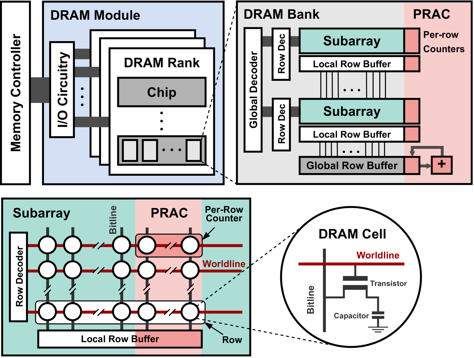
The image depicts a hierarchical representation of DRAM (Dynamic Random-Access Memory) architecture, divided into three primary sections:
1. **DRAM Module** (Top-left)
2. **DRAM Bank** (Top-right)
3. **Subarray/PRAC** (Bottom-left) with **DRAM Cell** inset (Bottom-right)
---
## 1. DRAM Module
### Components:
- **Memory Controller** (Vertical white bar on the left)
- Connects to **I/O Circuitry** (White rectangle with "I/O Circuitry" label)
- **DRAM Rank** (Gray rectangle)
- Contains multiple **Chip** components (Stacked gray rectangles with "Chip" labels)
- **Connections**:
- Dashed lines indicate hierarchical relationships between Memory Controller → I/O Circuitry → DRAM Rank → Chip
---
## 2. DRAM Bank
### Components:
- **Subarray** (Teal rectangles)
- Two instances labeled "Subarray"
- **Local Row Buffer** (White rectangles)
- Three instances labeled "Local Row Buffer"
- **Global Row Buffer** (Gray rectangle)
- Positioned at the bottom of the DRAM Bank
- **Decoders**:
- **Global Decoder** (Vertical white bar on the left)
- **Row Decoder** (Vertical white bar adjacent to Global Decoder)
- **PRAC** (Pink vertical bar on the right)
- Contains **Per-row Counters** (Pink rectangles with "+" symbols)
- **Connections**:
- Vertical lines connect Subarrays to Local Row Buffers
- Dashed lines link Local Row Buffers to Global Row Buffer
- PRAC connects to Global Row Buffer via a "+" symbol
---
## 3. Subarray/PRAC
### Subarray Structure:
- **Grid Layout**:
- 4x4 matrix of **Bitline** connections (White circles with red lines)
- **Row Decoder** (Vertical white bar on the left)
- **PRAC Column**:
- Pink vertical bar with **Per-row Counters** (Pink rectangles)
- **Local Row Buffer**:
- White rectangle at the bottom of the Subarray
- **Worldline** (Red horizontal line):
- Connects Bitlines to PRAC
### DRAM Cell Inset:
- **Components**:
- **Bitline** (Vertical black line)
- **Transistor** (Gray horizontal line with "Transistor" label)
- **Capacitor** (Gray vertical line with "Capacitor" label)
- **Worldline** (Red horizontal line connecting Bitline and Transistor)
---
## Color Coding & Spatial Grounding
| Component | Color | Spatial Position |
|--------------------|-------------|---------------------------------|
| DRAM Module | Blue | Top-left quadrant |
| DRAM Bank | Gray | Top-right quadrant |
| Subarray | Teal | Bottom-left quadrant |
| PRAC | Pink | Right side of Subarray/DRAM Bank|
| DRAM Cell | Black/Red | Bottom-right inset |
---
## Key Trends & Data Points
1. **Hierarchical Flow**:
- Memory Controller → I/O Circuitry → DRAM Rank → Chip (DRAM Module)
- Subarray → Local Row Buffer → Global Row Buffer (DRAM Bank)
- Bitline → Transistor → Capacitor (DRAM Cell)
2. **PRAC Functionality**:
- Per-row Counters (PRAC) monitor individual Subarray rows
- Connected to Global Row Buffer via summation ("+") symbol
3. **DRAM Cell Structure**:
- Worldline acts as a control line for the Transistor
- Capacitor stores charge for data retention
---
## Notes
- No explicit data table or numerical values present.
- All labels and components are in English.
- Diagram emphasizes structural relationships over quantitative data.