\n
## Diagram: Pruning Process Illustration
### Overview
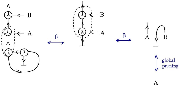
The image depicts a series of diagrams illustrating a pruning process, likely within a computational or algorithmic context. The diagrams show a transformation from a complex network structure to a simplified one, with labels indicating the steps and elements involved. The process appears to involve the removal of components based on parameters 'A' and 'B', and a 'global pruning' step.
### Components/Axes
The diagrams consist of nodes (represented as circles) connected by directed edges (arrows). The following labels are present:
* **A**: Appears at the bottom-right, and also as a label for an edge.
* **B**: Appears at the top-right, and also as a label for an edge.
* **λ (lambda)**: Appears within circles, representing a node type.
* **β (beta)**: Appears between the diagrams, indicating a transformation step.
* **global pruning**: Appears vertically on the right side, indicating a pruning operation.
* Dashed circle: Highlights a portion of the middle diagram.
### Detailed Analysis or Content Details
The diagrams can be broken down into three stages, moving from left to right:
**Stage 1 (Leftmost Diagram):**
* A complex network with multiple nodes.
* Two nodes are labeled 'λ'.
* An edge labeled 'A' connects to a node.
* An edge labeled 'B' connects to a node.
* A loop connects the two 'λ' nodes.
* A dashed line connects the two 'λ' nodes.
**Stage 2 (Middle Diagram):**
* A simplified network compared to Stage 1.
* A node labeled 'λ' is present.
* An edge labeled 'A' connects to the 'λ' node.
* An edge labeled 'B' connects to the 'λ' node.
* The 'λ' node is enclosed in a dashed circle.
* The transformation from Stage 1 to Stage 2 is indicated by 'β'.
**Stage 3 (Rightmost Diagram):**
* A further simplified network.
* Two edges, labeled 'A' and 'B', point upwards.
* An arc connects the end of edge 'B' back to the start of edge 'A'.
* The 'global pruning' operation is indicated by a double-headed arrow.
### Key Observations
* The diagrams demonstrate a progressive simplification of a network structure.
* The 'β' transformation appears to reduce the complexity of the network.
* The 'global pruning' step further simplifies the network, potentially removing redundant or less important components.
* The 'λ' nodes seem to be central to the pruning process, as they are present in the initial stages and are removed or simplified in subsequent stages.
* The dashed circle in Stage 2 highlights a specific portion of the network that is being targeted for pruning.
### Interpretation
The diagram illustrates a pruning algorithm or process used to reduce the complexity of a network. The parameters 'A' and 'B' likely represent criteria or thresholds used to determine which components to remove. The 'β' transformation represents a step in the pruning process, and the 'global pruning' step represents a final refinement. The use of 'λ' nodes suggests that these nodes are particularly susceptible to pruning, potentially representing redundant or less important elements in the network. The overall process aims to simplify the network while preserving its essential functionality. The diagram does not provide quantitative data, but rather a visual representation of the pruning process. The diagram suggests a hierarchical pruning approach, where initial pruning steps (β) are followed by a more global pruning operation. The dashed circle indicates a focus on specific network components during the pruning process.