## Diagram: Combinatory Logic Diagrams
### Overview
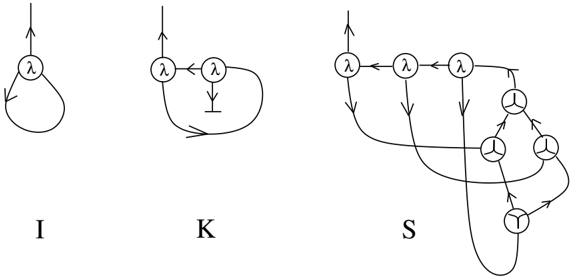
The image presents three diagrams labeled I, K, and S, representing combinatory logic expressions. Each diagram consists of circles containing the symbol "λ" or a "Y" shape, connected by lines with arrows indicating the direction of flow. The diagrams illustrate the reduction rules for the I, K, and S combinators.
### Components/Axes
* **Nodes:** Circles containing either "λ" or a "Y" shape.
* **Edges:** Lines connecting the nodes, with arrows indicating the direction of flow.
* **Labels:** "I", "K", and "S" are located below each diagram.
* **Input/Output:** Each diagram has a single input at the top and outputs indicated by arrows.
### Detailed Analysis
**Diagram I:**
* A circle containing "λ" is connected to itself by a loop with an arrow.
* An input arrow points towards the circle from the top.
* An output arrow emerges from the circle, pointing upwards.
**Diagram K:**
* Two circles, each containing "λ", are connected by an arrow pointing from the left circle to the right circle.
* A line with a short perpendicular line segment (representing deletion) points downwards from the right circle.
* A curved arrow connects the right circle back to the left circle.
* An input arrow points towards the left circle from the top.
* An output arrow emerges from the left circle, pointing upwards.
**Diagram S:**
* Three circles containing "λ" are arranged horizontally, connected by arrows pointing from left to right.
* The rightmost circle containing "λ" has a line extending downwards, leading to a tree-like structure composed of four "Y" shaped nodes.
* The "Y" nodes are connected by arrows, forming a binary tree structure.
* Arrows connect the leftmost and middle "λ" circles to the bottom "Y" node.
* An input arrow points towards the leftmost circle from the top.
* An output arrow emerges from the top-left "λ" circle, pointing upwards.
### Key Observations
* The diagrams visually represent the reduction rules of the I, K, and S combinators.
* The "λ" nodes likely represent lambda abstractions.
* The "Y" nodes likely represent application.
* The arrows indicate the flow of data or computation.
### Interpretation
The diagrams illustrate the fundamental combinators I, K, and S, which are essential components of combinatory logic. Combinatory logic is a notation for expressing mathematical logic without using variable names. The diagrams provide a visual representation of how these combinators transform expressions. The I combinator represents identity, the K combinator represents a constant function, and the S combinator represents substitution. The tree-like structure in the S combinator diagram suggests a more complex transformation involving multiple applications. These diagrams are useful for understanding the underlying mechanisms of functional programming and lambda calculus.