## Diagram: Three-Step Query Processing Workflow with RAG
### Overview
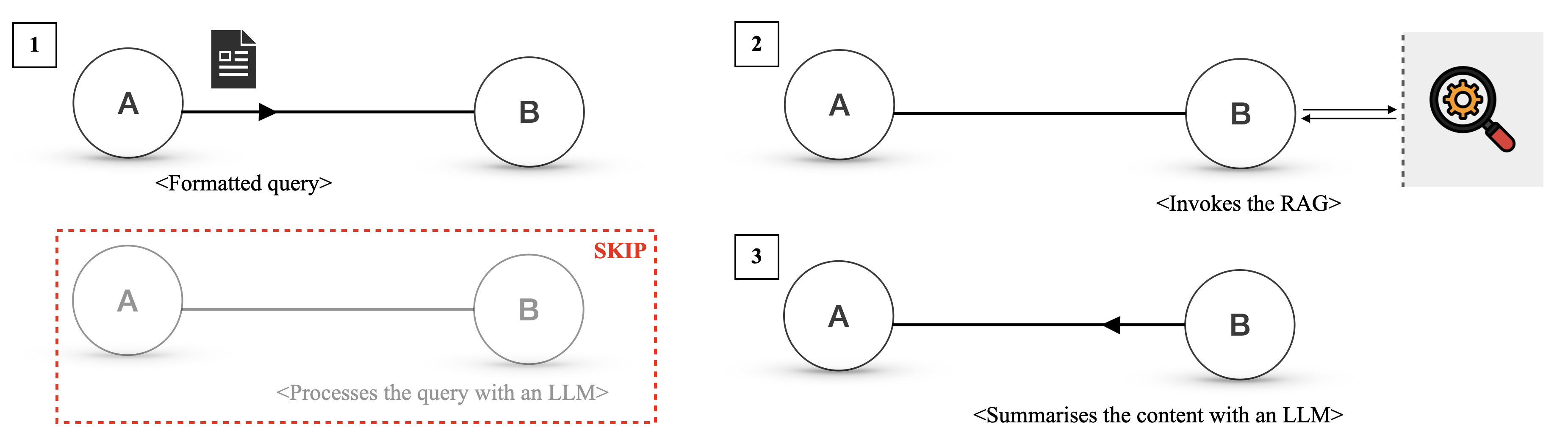
The image is a technical diagram illustrating a three-step workflow for processing a query, involving two primary entities labeled "A" and "B". The diagram is divided into three numbered panels (1, 2, 3) arranged horizontally, with an additional faded, dashed-red-boxed panel below panel 1 labeled "SKIP". The overall flow depicts a sequence where a query is formatted, a Retrieval-Augmented Generation (RAG) system is invoked, and finally, content is summarized.
### Components/Axes
* **Primary Entities:** Two circles labeled **A** and **B** appear in each step. They represent actors or components in the system.
* **Numbered Steps:** Each major interaction is labeled with a number in a square box in the top-left corner of its panel: **1**, **2**, and **3**.
* **Icons:**
* A **document icon** (black with white lines) appears above the arrow in Step 1.
* A **magnifying glass icon** with an orange gear inside appears to the right of Step 2, enclosed in a light gray box with a dashed left border.
* **Arrows:** Directional arrows indicate the flow of data or commands between entities.
* **Text Annotations:** Descriptive text in angle brackets (`< >`) is placed below or near the arrows to describe the action.
* **"SKIP" Panel:** A faded, grayed-out version of the Step 1 diagram is enclosed in a **red dashed rectangle**. The word **"SKIP"** is written in red, bold, uppercase letters at the top-right corner of this rectangle.
### Detailed Analysis
The diagram details a specific sequence of operations:
**Step 1 (Top-Left Panel):**
* **Flow:** An arrow points from **A** to **B**.
* **Visual Element:** A document icon is positioned above the arrow.
* **Text Annotation:** Below the arrow, the text reads: `<Formatted query>`.
* **Interpretation:** Entity A sends a formatted query to Entity B.
**Step 2 (Top-Right Panel):**
* **Flow:** A double-headed arrow (pointing both left and right) connects **B** to the magnifying glass icon.
* **Visual Element:** The magnifying glass with a gear is inside a gray box, suggesting an external system or service.
* **Text Annotation:** Below the arrow, the text reads: `<Invokes the RAG>`.
* **Interpretation:** Entity B interacts bidirectionally with a RAG (Retrieval-Augmented Generation) system, likely to retrieve relevant information.
**Step 3 (Bottom-Right Panel):**
* **Flow:** An arrow points from **B** back to **A**.
* **Text Annotation:** Below the arrow, the text reads: `<Summarises the content with an LLM>`.
* **Interpretation:** Entity B sends a summary back to Entity A. The summary is generated using a Large Language Model (LLM).
**"SKIP" Panel (Bottom-Left, below Step 1):**
* **Visual State:** The circles for A and B and the connecting arrow are faded to light gray.
* **Bounding Box:** The entire panel is enclosed in a red dashed rectangle.
* **Label:** The word **"SKIP"** is prominently displayed in red.
* **Text Annotation:** Below the faded arrow, the text reads: `<Processes the query with an LLM>`.
* **Interpretation:** This panel represents an alternative or previous step that is being bypassed or omitted in the current workflow. Instead of directly processing the query with an LLM (as shown here), the workflow proceeds through the RAG invocation in Steps 1-2-3.
### Key Observations
1. **Sequential Flow:** The numbered steps (1 → 2 → 3) define a clear, linear process.
2. **Role of RAG:** The RAG system is invoked as an intermediate step (Step 2) between receiving the query and returning the summary. This suggests the system retrieves external or specific knowledge before generation.
3. **LLM Usage:** The LLM is explicitly mentioned in two contexts: in the "SKIP" panel for direct query processing, and in Step 3 for summarization. This implies the LLM's role is focused on synthesis (summarization) rather than initial query handling in the active workflow.
4. **Visual Emphasis on "SKIP":** The use of red color, dashed lines, and fading strongly indicates that the direct "Processes the query with an LLM" path is not taken in this specific process flow.
### Interpretation
This diagram illustrates a **Retrieval-Augmented Generation (RAG) pipeline** for query answering. The core narrative is the replacement of a direct LLM query processing step with a more sophisticated retrieval-then-summarize approach.
* **What it demonstrates:** The workflow shows how a system (represented by A and B) can generate more informed or accurate responses by first retrieving relevant documents or data (via the RAG system in Step 2) before using an LLM to synthesize a summary (Step 3). The "SKIP" panel highlights this architectural choice, contrasting the RAG-based method with a simpler, direct LLM call.
* **Relationships:** Entity A appears to be the initiator/client (sends query, receives summary). Entity B acts as the orchestrator or processor (receives query, calls RAG, manages summarization). The RAG system is an external tool or database.
* **Notable Implication:** The diagram argues for the value of grounding LLM responses in retrieved information. By skipping the direct LLM processing and instead invoking RAG, the system likely aims to reduce hallucinations, improve factual accuracy, and incorporate up-to-date or domain-specific knowledge that the base LLM might not possess. The final output is not the raw retrieved data but a summarized synthesis, indicating the LLM's role is to digest and present the retrieved information coherently.