## Directed Graph Diagram: System State or Dependency Map
### Overview
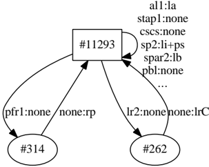
The image displays a directed graph diagram, likely representing a system state, dependency map, or workflow. It consists of one central rectangular node, two peripheral oval nodes, and directed edges (arrows) connecting them. Text labels are associated with the nodes and edges, suggesting attributes, conditions, or transition rules. The diagram is rendered in black and white with a hand-drawn or sketched aesthetic.
### Components/Axes
* **Nodes:**
* **Central Node:** A rectangle positioned in the upper-center of the image. It contains the label `#11293`.
* **Bottom-Left Node:** An oval positioned in the lower-left quadrant. It contains the label `#314`.
* **Bottom-Right Node:** An oval positioned in the lower-right quadrant. It contains the label `#262`.
* **Edges (Arrows):**
* A curved arrow points from the central node (`#11293`) to the bottom-left node (`#314`). This edge carries two text labels: `pfr1:none` (positioned near the start of the arrow) and `none:rp` (positioned near the arrowhead).
* A curved arrow points from the bottom-left node (`#314`) back to the central node (`#11293`). This edge has no visible text label.
* A curved arrow points from the central node (`#11293`) to the bottom-right node (`#262`). This edge carries two text labels: `lr2:none` (near the start) and `none:lrC` (near the arrowhead).
* A curved arrow points from the bottom-right node (`#262`) back to the central node (`#11293`). This edge has no visible text label.
* **Text Block (Legend/Attributes):** A list of key-value pairs is positioned to the immediate right of the central node (`#11293`). The text is aligned vertically. The full list is:
* `al1:la`
* `stap1:none`
* `cscs:none`
* `sp2:li-ps`
* `spar2:lb`
* `pbl:none`
* `...` (an ellipsis, indicating the list is truncated or continues).
### Detailed Analysis
* **Node Identification:** Nodes are identified by unique alphanumeric codes prefixed with a hash symbol (`#`). The central node is `#11293`. The two subordinate nodes are `#314` and `#262`.
* **Edge Label Structure:** The labels on the edges follow a `key:value` or `source:target` format.
* Edge `#11293` -> `#314`: Labels are `pfr1:none` and `none:rp`. This could indicate a transition condition where `pfr1` is `none` and the result or target state is `rp`.
* Edge `#11293` -> `#262`: Labels are `lr2:none` and `none:lrC`. This could indicate a transition where `lr2` is `none` and the result is `lrC`.
* **Attribute List:** The text block to the right of node `#11293` appears to be a list of attributes or properties associated with that specific node. Each line is a `property:state` pair (e.g., `stap1:none`, `sp2:li-ps`). The ellipsis (`...`) confirms this is a partial view of a longer list.
### Key Observations
1. **Bidirectional Flow:** The graph shows a closed loop or bidirectional relationship between the central node (`#11293`) and each of the two peripheral nodes (`#314`, `#262`). This suggests a two-way interaction, state transition, or dependency.
2. **Central Hub:** Node `#11293` acts as a hub, connecting to two other nodes. It is the only node with an associated attribute list, implying it is the primary subject of the diagram.
3. **Label Asymmetry:** The edges from the hub to the peripheral nodes are labeled with conditions (`key:none`), while the return edges are unlabeled. This may indicate that the forward transitions are conditional or have specific parameters, while the return paths are default or unconditional.
4. **Ellipsis Implication:** The `...` in the attribute list explicitly states that the information presented is incomplete, hinting at a larger, more complex system state than what is shown.
### Interpretation
This diagram is a technical representation of a system's state or component relationships. The `#` prefixed codes likely represent unique identifiers for processes, modules, states, or data objects within a software system, network protocol, or workflow engine.
* **What it suggests:** The diagram illustrates that entity `#11293` is in a specific state defined by multiple attributes (like `al1:la`, `stap1:none`). It can transition to entity `#314` under the condition `pfr1:none`, resulting in state `rp`. Similarly, it can transition to entity `#262` under condition `lr2:none`, resulting in state `lrC`. Both `#314` and `#262` can, in turn, transition back to `#11293`.
* **Relationships:** The structure is a star topology with a central hub (`#11293`) and two spokes (`#314`, `#262`). The hub is the most information-rich component. The relationships are defined by conditional, directed transitions.
* **Anomalies/Notable Points:** The lack of labels on the return paths is the most significant anomaly. It raises questions: Are these return transitions automatic? Are they not the focus of this particular view? The ellipsis is also critical, as it warns the viewer that the state of `#11293` is more complex than depicted, and conclusions drawn from this partial view may be incomplete.
**In essence, this is a snapshot of a state machine or dependency graph, highlighting the conditional pathways from a central, well-defined state (`#11293`) to two other states, while explicitly noting that the full definition of the central state is not shown.**