## Diagram: Path Comparison (Optimal vs. Model)
### Overview
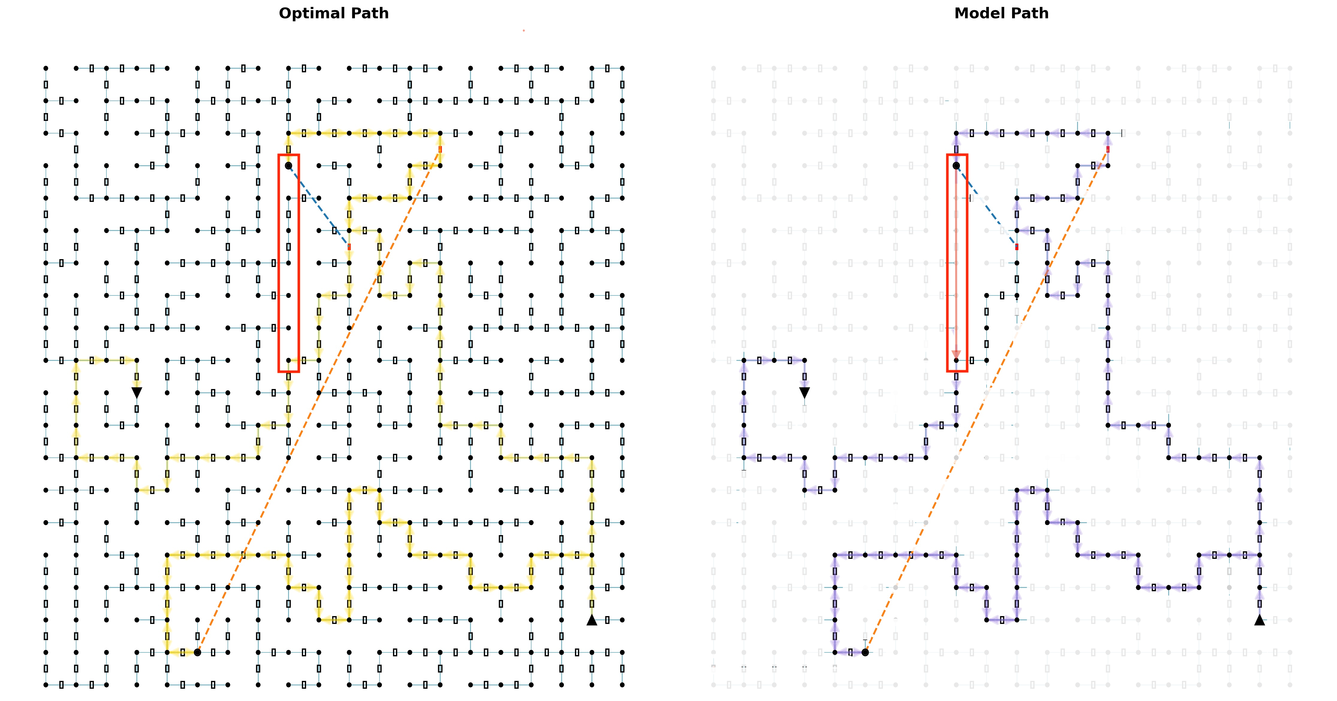
The image presents two side-by-side panels labeled **"Optimal Path"** (left) and **"Model Path"** (right). Both panels depict a grid of interconnected nodes with directional paths, highlighted by colored lines, arrows, and annotations. The panels share a common red dashed line and blue dotted line, suggesting a comparison of two strategies or algorithms.
---
### Components/Axes
- **Grid Structure**:
- Both panels feature a grid of black nodes connected by thin lines.
- Nodes are arranged in a 2D lattice, with coordinates implied by their positions (e.g., (3,5), (7,9)).
- **Paths**:
- **Optimal Path (Left)**:
- Yellow lines with arrows indicate a complex, zigzagging route.
- A red dashed line traces a diagonal from (3,5) to (7,5), then a blue dotted line extends vertically to (7,9).
- **Model Path (Right)**:
- Purple lines with arrows show a simpler, more direct route.
- The same red dashed line and blue dotted line are present, but the blue line ends at (7,7).
- **Annotations**:
- Red boxes highlight nodes at (3,5) and (7,5).
- Black triangles mark endpoints at (7,9) (optimal) and (7,7) (model).
- **Legend**:
- Located in the top-right corner of both panels.
- Colors correspond to:
- **Red dashed line**: Shared reference path.
- **Blue dotted line**: Divergent path (optimal vs. model).
- **Yellow/purple lines**: Path directions (optimal/model).
---
### Detailed Analysis
#### Optimal Path (Left)
- **Key Features**:
- The yellow path starts at (3,5), follows the red dashed line to (7,5), then ascends vertically via the blue dotted line to (7,9).
- Arrows indicate movement direction, with frequent turns and backtracking.
- A red box highlights the starting node (3,5), and a black triangle marks the endpoint (7,9).
- **Trends**:
- The path is longer and more convoluted compared to the model path.
- The blue dotted line represents a critical upward trajectory, suggesting a focus on reaching higher nodes.
#### Model Path (Right)
- **Key Features**:
- The purple path starts at (3,5), follows the red dashed line to (7,5), then ascends vertically via the blue dotted line to (7,7).
- Arrows show a more linear progression with fewer turns.
- A red box highlights the starting node (3,5), and a black triangle marks the endpoint (7,7).
- **Trends**:
- The path is shorter and more direct, terminating at a lower node (7,7) compared to the optimal path.
---
### Key Observations
1. **Shared Reference Path**:
- Both panels share the red dashed line from (3,5) to (7,5), indicating a common initial route.
2. **Divergence at (7,5)**:
- The blue dotted line splits at (7,5):
- **Optimal Path**: Continues upward to (7,9).
- **Model Path**: Ends at (7,7).
3. **Path Complexity**:
- The optimal path includes more turns and backtracking (yellow lines), while the model path is streamlined (purple lines).
4. **Endpoint Differences**:
- The optimal path reaches a higher node (7,9), whereas the model path stops at (7,7).
---
### Interpretation
- **Optimal vs. Model Trade-offs**:
- The optimal path prioritizes reaching a higher endpoint (7,9) but at the cost of increased complexity and length.
- The model path sacrifices endpoint height for simplicity and efficiency, terminating at (7,7).
- **Red Dashed Line Significance**:
- Acts as a baseline or constraint, shared by both paths, suggesting it represents a mandatory or preferred route.
- **Blue Dotted Line Role**:
- Represents the critical decision point where the two strategies diverge. The optimal path extends further, while the model path stops earlier.
- **Annotations**:
- Red boxes and triangles emphasize key nodes, possibly indicating decision points, obstacles, or goals.
---
### Conclusion
The diagram illustrates a trade-off between path efficiency and endpoint optimization. The optimal path achieves a higher goal but with greater complexity, while the model path prioritizes simplicity at the expense of reaching a lower endpoint. The shared red dashed line and divergent blue dotted line highlight the critical decision point in the pathfinding process.