## System Architecture Diagram: Service Integration Patterns
### Overview
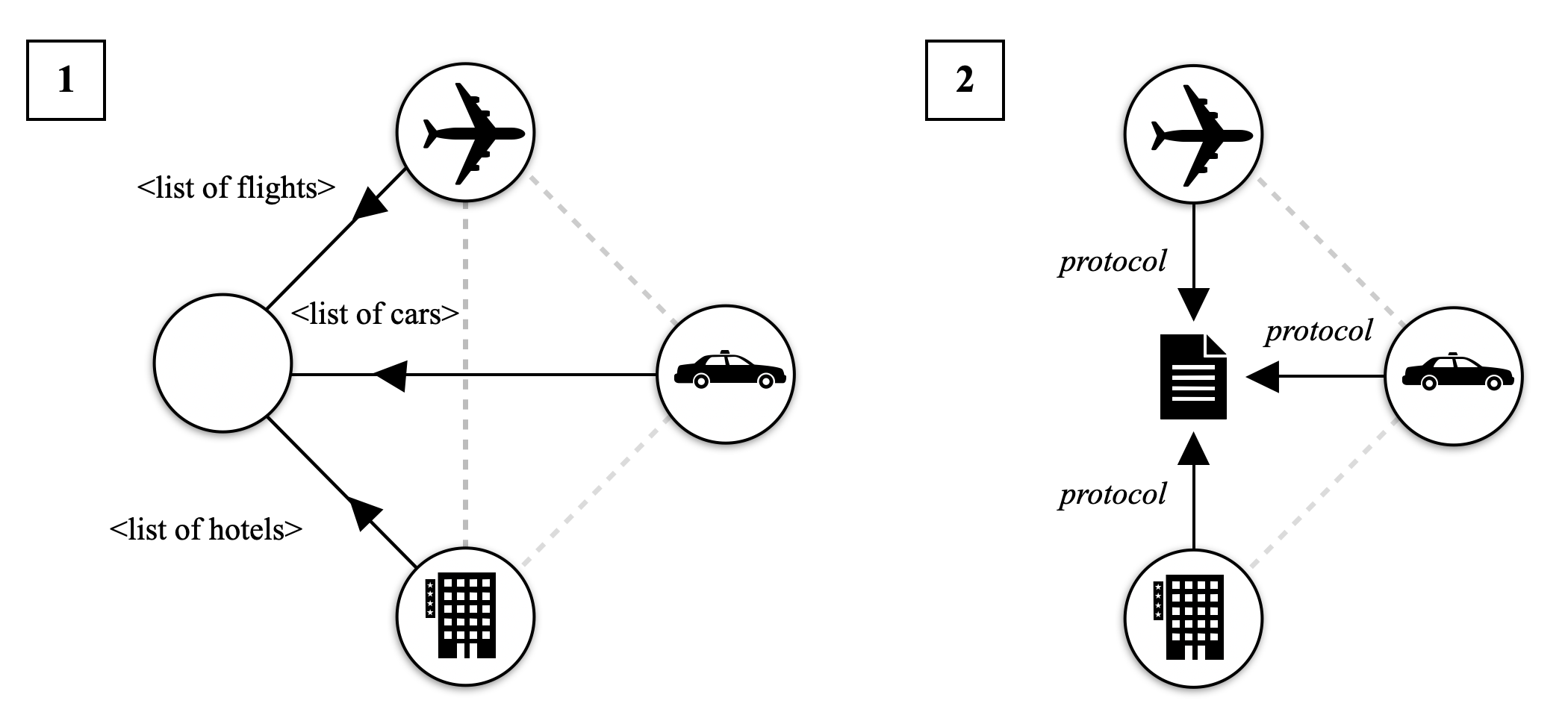
The image displays two side-by-side diagrams, labeled "1" and "2", illustrating contrasting architectural patterns for integrating travel-related services (flights, cars, hotels). Both diagrams use identical service icons but depict fundamentally different communication and data flow structures.
### Components/Axes
**Common Elements (Both Diagrams):**
* **Service Icons:** Three circular icons representing external services:
* **Airplane Icon:** Represents a flight service.
* **Car Icon:** Represents a car rental service.
* **Building Icon:** Represents a hotel service.
* **Connecting Lines:** Dashed gray lines connect the three service icons to each other in a triangular formation, suggesting a potential peer relationship or network.
**Diagram 1 (Left):**
* **Central Node:** A large, empty circle positioned to the left of the service icons.
* **Data Flow Arrows:** Three solid black arrows point **from** the service icons **to** the central node.
* **Labels on Arrows:**
* Arrow from Airplane Icon: `<list of flights>`
* Arrow from Car Icon: `<list of cars>`
* Arrow from Hotel Icon: `<list of hotels>`
**Diagram 2 (Right):**
* **Central Mediator:** A black document icon (resembling a contract or specification file) positioned in the center of the service triangle.
* **Protocol Arrows:** Three solid black arrows point **from** each service icon **to** the central document icon.
* **Labels on Arrows:** Each arrow is labeled with the word `protocol` in italics.
### Detailed Analysis
**Diagram 1: Direct Data Aggregation Pattern**
* **Structure:** A hub-and-spoke model. The central node acts as an aggregator or client.
* **Flow Direction:** Unidirectional. Data flows from each external service (Airplane, Car, Building) directly to the central aggregator.
* **Data Exchanged:** The labels specify the exact data payloads: `<list of flights>`, `<list of cars>`, and `<list of hotels>`. This implies the central node receives raw, service-specific data lists.
* **Relationship:** The dashed lines between services are present but unused in this flow, indicating the services do not communicate directly with each other in this pattern.
**Diagram 2: Protocol-Mediated Integration Pattern**
* **Structure:** A mediator or broker model. The central document icon represents a shared protocol, standard, or interface specification.
* **Flow Direction:** Unidirectional. Each external service communicates its data or capabilities **to** the central protocol definition.
* **Data Exchanged:** The label `protocol` on each arrow indicates that services are not sending raw data lists, but are instead adhering to or publishing to a common communication standard or contract.
* **Relationship:** Similar to Diagram 1, the dashed lines between services are present but unused, showing the protocol is the sole point of integration.
### Key Observations
1. **Identical Components, Different Topology:** The core difference is the replacement of the generic aggregator node (empty circle) in Diagram 1 with a specific protocol/document icon in Diagram 2.
2. **Shift in Abstraction:** Diagram 1 focuses on the **data** being transferred (`<list of...>`). Diagram 2 focuses on the **rules** for communication (`protocol`).
3. **Arrow Direction Consistency:** In both diagrams, arrows point from the services to the central element, indicating a "push" or "publish" model from the services' perspective.
4. **Visual Emphasis:** The central document icon in Diagram 2 is filled and prominent, visually emphasizing the protocol as the critical, defining component of that architecture.
### Interpretation
This diagram contrasts two fundamental approaches to system integration in a multi-service environment (e.g., a travel booking platform).
* **Diagram 1 represents a tightly-coupled, point-to-point integration style.** The central system must understand and handle the specific data format of each service (`<list of flights>` is different from `<list of cars>`). This can lead to complex, brittle code in the central aggregator as each new service requires custom integration logic. The pattern is simple but does not scale well.
* **Diagram 2 represents a loosely-coupled, standardized integration style.** By introducing a common `protocol`, the architecture decouples the services from the central system. Each service only needs to conform to the shared protocol. This promotes interoperability, simplifies the central system's logic (it only needs to understand one protocol), and makes adding or changing services easier. The protocol acts as a **contract**, enabling a more modular and maintainable system.
**Underlying Message:** The progression from 1 to 2 illustrates a design evolution from custom data aggregation to standardized interface-based communication. It argues for the benefits of defining clear protocols to manage complexity in distributed systems. The unused dashed lines between services hint that a future evolution (Diagram 3?) might involve direct service-to-service communication using the same established protocol.