## Arithmetic Circuit (AC) Diagram
### Overview
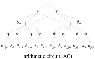
The image depicts a hierarchical arithmetic circuit (AC) structure represented as a tree diagram. The circuit is composed of interconnected nodes labeled with mathematical symbols, variables, and operations. The diagram emphasizes symmetry and hierarchical relationships, with operations (e.g., addition) and variables (e.g., θ, λ, x, y) distributed across levels.
### Components/Axes
- **Title**: "arithmetic circuit (AC)" (bottom center).
- **Nodes**:
- **Top Layer**: A single "+" node (root).
- **Second Layer**: Two nodes labeled θ_u (left) and θ_ū (right).
- **Third Layer**: Four nodes:
- Left branch: θ_x|u, λ_x, θ_x|ū, λ_ū.
- Right branch: θ_y|u, λ_y, θ_y|ū, λ_ū.
- **Bottom Layer**: Eight terminal nodes (leaf nodes) labeled with variables and operations (e.g., θ_x|u, λ_x, θ_x|ū, λ_ū, θ_y|u, λ_y, θ_y|ū, λ_ū).
- **Connections**: Lines between nodes indicate operational flow (e.g., addition at "+" nodes).
### Detailed Analysis
- **Root Node**: The "+" symbol at the top suggests the circuit aggregates results from its subtrees.
- **θ_u and θ_ū**: These nodes likely represent parameters or functions applied to inputs u and ū, respectively.
- **Third-Layer Nodes**:
- θ_x|u and θ_x|ū: Variables or functions conditioned on inputs u and ū.
- λ_x and λ_ū: Possibly transformation or weighting parameters.
- **Bottom-Layer Nodes**: Terminal nodes combine variables (x, y) with operations (θ, λ) and conditioning (u, ū).
- **Symmetry**: The left and right branches mirror each other, with x and y variables processed identically.
### Key Observations
1. **Hierarchical Structure**: The circuit processes inputs through layered operations, culminating in a final output at the root.
2. **Conditional Variables**: Subscripts like |u and |ū indicate dependencies on specific inputs.
3. **Redundancy**: Duplicate labels (e.g., λ_ū appearing in both branches) suggest shared parameters or parallel processing.
4. **No Numerical Data**: The diagram is symbolic, with no explicit numerical values or trends.
### Interpretation
This arithmetic circuit diagram illustrates a computational framework for combining variables (x, y) through parameterized operations (θ, λ) conditioned on inputs (u, ū). The symmetry implies parallelism or redundancy, while the hierarchical design enables modular computation. The use of θ and λ may denote learnable parameters (e.g., in machine learning) or fixed constants, depending on context. The absence of numerical values suggests the diagram is a conceptual or architectural representation rather than a data-driven visualization.