## Arithmetic Circuit Diagram
### Overview
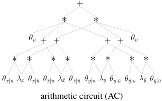
The image presents a diagram of an arithmetic circuit (AC). It depicts a hierarchical structure of mathematical operations, specifically additions (+) and multiplications (*), applied to various input variables and parameters. The diagram illustrates the flow of computation from the bottom (inputs) to the top (final result).
### Components/Axes
* **Nodes:** The diagram consists of nodes representing mathematical operations (+ and *).
* **Inputs:** The bottom layer of the diagram shows the input variables and parameters, denoted as:
* θx|u
* λx
* θx|ū
* θx|ū
* λx
* θx|ū
* θy|u
* λy
* θy|ū
* θy|ū
* λy
* θy|ū
* **Intermediate Variables:** Intermediate variables are represented by θu and θū.
* **Operations:** The diagram shows alternating layers of multiplication (*) and addition (+) operations.
* **Output:** The top node represents the final result of the arithmetic circuit, denoted by a plus sign (+).
### Detailed Analysis
The arithmetic circuit diagram is structured as follows:
1. **Bottom Layer (Inputs):** The inputs are arranged linearly at the bottom.
2. **First Layer of Multiplications:** Each pair of adjacent inputs is multiplied.
3. **First Layer of Additions:** The results of the multiplications are added in pairs.
4. **Second Layer of Multiplications:** The results of the additions are multiplied.
5. **Second Layer of Additions:** The results of the multiplications are added.
6. **Top Node (Output):** The final result is obtained at the top node.
### Key Observations
* The diagram illustrates a specific arithmetic circuit with a fixed structure.
* The circuit involves a combination of multiplication and addition operations.
* The inputs consist of variables and parameters related to x, y, u, and ū.
### Interpretation
The arithmetic circuit diagram represents a computational process where inputs are combined through a series of multiplications and additions to produce a final result. The specific structure of the circuit determines the mathematical function it computes. The diagram provides a visual representation of the flow of computation and the relationships between different variables and operations. The circuit likely represents a specific mathematical function or algorithm, possibly related to machine learning or signal processing. The parameters θ and λ likely represent weights or coefficients in the computation.