## Diagram: Two-Link Kinematic Model
### Overview
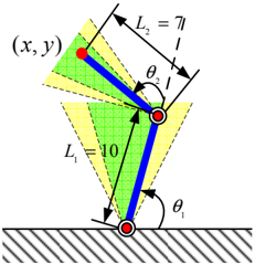
This image displays a technical diagram illustrating a two-link kinematic chain, likely representing a robotic arm or a leg segment. It shows two rigid links connected by revolute joints, with defined lengths, angles, and an end-effector coordinate. Shaded regions indicate possible ranges of motion or a workspace.
### Components/Axes
The diagram is set against a plain white background.
* **Links**:
* A lower link, colored blue, is labeled with length `L₁ = 10`. It extends upwards from a base joint.
* An upper link, also colored blue, is labeled with length `L₂ = 7`. It extends upwards and slightly to the left from a middle joint, connecting to the lower link.
* **Joints/Pivot Points**: Represented by red filled circles.
* **Bottom Joint**: Located at the bottom-center, resting on a hatched horizontal surface. This is the base or fixed joint.
* **Middle Joint**: Connects the lower link (L₁) and the upper link (L₂).
* **Top Joint**: The end-effector of the upper link (L₂), located at the top-left.
* **Angles**:
* `θ₁`: An angle measured counter-clockwise from a vertical dashed line (extending upwards from the bottom joint) to the lower link (L₁). It is an acute angle.
* `θ₂`: An angle measured clockwise from a vertical dashed line (extending upwards from the middle joint) to the upper link (L₂). It is an acute angle.
* **Coordinates**:
* `(x, y)`: A label positioned to the top-left of the top joint, indicating the Cartesian coordinates of the end-effector.
* **Reference Lines**:
* Two vertical dashed lines extend upwards from the bottom and middle joints, serving as reference axes for angles `θ₁` and `θ₂` respectively.
* Dashed lines also define the boundaries of the shaded regions, indicating extreme positions or ranges.
* **Surface**: A horizontal hatched line at the very bottom of the diagram, representing a ground or base surface upon which the bottom joint rests.
* **Shaded Regions**:
* **Green Shaded Region**: A triangular area originating from the middle joint, extending upwards and to the left. It is bounded by the upper link (L₂) in its current position and a dashed line representing an extreme position. This suggests a specific operational range or configuration.
* **Yellow Shaded Regions**: Multiple triangular areas.
* One originating from the middle joint, extending upwards and to the right, adjacent to the green region.
* Two originating from the bottom joint, extending upwards, one to the left and one to the right of the lower link (L₁). These regions, bounded by dashed lines, likely represent the full possible range of motion for each link or joint.
### Detailed Analysis
The diagram illustrates a planar two-degree-of-freedom (2-DOF) manipulator.
* The lower link (L₁) has a length of 10 units.
* The upper link (L₂) has a length of 7 units.
* The bottom joint is fixed to the ground.
* Angle `θ₁` defines the orientation of the first link relative to the vertical.
* Angle `θ₂` defines the orientation of the second link relative to the first link (or relative to a vertical reference from the middle joint, as drawn).
* The end-effector's position is denoted by `(x, y)`.
* The green shaded area, originating from the middle joint, suggests a specific angular range for `θ₂` or a target workspace segment. The yellow shaded areas, originating from both joints, indicate the broader possible angular ranges for `θ₁` and `θ₂`, showing the limits of their rotation. The dashed lines within these shaded areas represent the boundaries of these ranges.
### Key Observations
* The system is a serial kinematic chain with two revolute joints.
* Link lengths L₁ and L₂ are explicitly given as 10 and 7, respectively.
* Joint angles θ₁ and θ₂ are clearly marked, indicating the degrees of freedom.
* The end-effector's position (x, y) is identified.
* The shaded regions visually represent the workspace or angular limits, with green possibly highlighting a current or target operational zone, and yellow showing the full potential range.
### Interpretation
This diagram is a fundamental representation used in robotics, biomechanics, or mechanical engineering to model a two-link system.
* **Kinematic Analysis**: It provides the necessary parameters (link lengths L₁, L₂ and joint angles θ₁, θ₂) to perform forward kinematics (calculating (x, y) from L₁, L₂, θ₁, θ₂) or inverse kinematics (calculating θ₁, θ₂ from L₁, L₂, (x, y)).
* **Workspace Visualization**: The shaded regions are crucial for understanding the reachable space of the end-effector. The yellow regions likely depict the maximum possible angular sweep for each link, while the green region might represent a specific task space, a safe operating zone, or a current configuration's immediate reach. The dashed lines within these regions denote the boundaries of these ranges, suggesting that the links can pivot between these extreme positions.
* **System Configuration**: The specific values for L₁ and L₂ (10 and 7) indicate a non-uniform link length system, which affects the shape and size of the workspace. The current configuration shown by the blue links and red joints is one specific pose within the possible range of motion.
* **Application**: Such a model could represent a simplified human leg (thigh and calf), a robotic arm segment, or a mechanism in a machine, where understanding the position, orientation, and reachable space is critical for design, control, and task planning.