\n
## Diagram: Robotic Arm Kinematics
### Overview
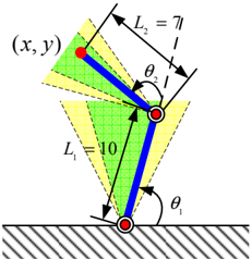
The image depicts a schematic diagram of a two-link robotic arm, illustrating its kinematic parameters. The diagram shows the arm anchored to a base, with two links (L1 and L2) connected by a joint. The end-effector's position is denoted by (x, y). The diagram also shows the angles θ1 and θ2, representing the joint angles. Yellow shaded regions indicate the workspace reachable by the end-effector.
### Components/Axes
* **Base:** The horizontal, textured gray area at the bottom of the diagram represents the base of the robotic arm.
* **Link 1 (L1):** The green line segment extending from the base to the first joint. L1 is labeled as having a length of 10 units.
* **Link 2 (L2):** The blue line segment extending from the first joint to the end-effector. L2 is labeled as having a length of 7 units.
* **Joint 1:** The red circle where Link 1 connects to the base.
* **Joint 2:** The red circle where Link 1 connects to Link 2.
* **End-Effector:** The red circle at the end of Link 2, with coordinates (x, y).
* **Angle θ1:** The angle between Link 1 and the vertical axis, measured at Joint 1.
* **Angle θ2:** The angle between Link 2 and the line connecting Joint 1 and Joint 2, measured at Joint 2.
* **Workspace:** The yellow shaded areas represent the reachable workspace of the end-effector.
* **Grid:** A faint grid pattern is visible in the background, providing a visual reference for position.
### Detailed Analysis
The diagram illustrates the forward kinematics of a 2R (two revolute joint) planar robotic arm. The lengths of the links are explicitly given: L1 = 10 and L2 = 7. The coordinates (x, y) represent the position of the end-effector, which is a function of the joint angles θ1 and θ2 and the link lengths. The yellow shaded areas represent the workspace, which is the set of all points that the end-effector can reach given the constraints of the link lengths and joint limits.
The diagram does not provide specific numerical values for x, y, θ1, or θ2. It is a conceptual illustration of the arm's geometry.
### Key Observations
* The workspace is limited by the link lengths. Shorter links result in a smaller workspace.
* The diagram shows the potential for multiple configurations of the arm to reach the same point in space (due to the overlapping yellow regions).
* The grid provides a visual scale, but no specific units are indicated.
### Interpretation
This diagram is a fundamental representation used in robotics to understand the relationship between joint angles and end-effector position. It demonstrates the concept of kinematic chains and the importance of link lengths and joint angles in determining the arm's reach and dexterity. The workspace visualization is crucial for task planning, ensuring that the robot can reach all necessary points within its environment. The diagram is a simplified model, neglecting factors such as link thickness, joint friction, and actuator limits, but it provides a valuable starting point for analyzing and controlling robotic arm movements. The diagram is a visual aid for understanding the mathematical equations that govern the arm's kinematics.