## Diagram: Two-Link Planar Robotic Arm / Kinematic Chain
### Overview
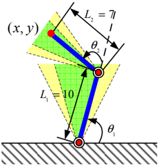
The image is a technical schematic diagram illustrating a two-link planar manipulator, a fundamental model in robotics and kinematics. It depicts a mechanical arm with two rigid segments (links) connected by revolute joints, fixed to a ground base. The diagram defines the geometric parameters and variables used to calculate the position of the end-effector (the tip of the second link).
### Components/Axes
* **Base:** A fixed ground, represented by a hatched horizontal line at the bottom of the diagram.
* **Link 1 (L₁):** The first rigid segment, colored blue. It is connected to the base at a fixed joint.
* **Label:** `L₁ = 10` (indicating its length is 10 units).
* **Joint 1:** The connection point between the base and Link 1. It allows rotational motion.
* **Link 2 (L₂):** The second rigid segment, also colored blue. It is connected to the end of Link 1.
* **Label:** `L₂ = 7` (indicating its length is 7 units).
* **Joint 2:** The connection point between Link 1 and Link 2. It allows rotational motion.
* **End-Effector:** The terminal point of the kinematic chain, marked with a red dot.
* **Label:** `(x, y)` representing its coordinates in a 2D Cartesian plane.
* **Angles (Joint Variables):**
* `θ₁`: The angle of Link 1 relative to the horizontal ground. An arc with an arrow indicates this angle is measured counter-clockwise from the horizontal axis to the centerline of Link 1.
* `θ₂`: The relative angle between Link 1 and Link 2. An arc with an arrow indicates this angle is measured from the extension of Link 1's centerline to the centerline of Link 2.
* **Workspace Indicators:** Two shaded, fan-shaped regions (one green, one yellow) emanate from the joints. These likely represent the reachable workspace or angular limits for each link.
### Detailed Analysis
The diagram establishes a standard forward kinematics model for a 2-degree-of-freedom (2-DOF) planar robot.
1. **Geometric Relationships:** The position `(x, y)` of the end-effector is a function of the fixed link lengths (`L₁`, `L₂`) and the variable joint angles (`θ₁`, `θ₂`).
2. **Angle Definitions:**
* `θ₁` is the **absolute angle** of the first link.
* `θ₂` is the **relative angle** of the second link with respect to the first.
3. **Spatial Layout:**
* The base joint is at the origin of the implied coordinate system (bottom-center).
* Link 1 extends upward and to the left from the base.
* Link 2 extends further upward and to the left from the end of Link 1.
* The end-effector `(x, y)` is located at the top-left of the diagram.
* The angle arcs are positioned near their respective joints for clarity.
### Key Observations
* The system has **two degrees of freedom**, defined by the two independent angles `θ₁` and `θ₂`.
* The link lengths are **asymmetric** (`L₁=10`, `L₂=7`), which is a common configuration.
* The shaded regions suggest **constraints** on the joint angles, defining the permissible range of motion for each link.
* The diagram uses **color coding**: blue for rigid links, red for joints/end-effector, and green/yellow for workspace zones.
### Interpretation
This diagram is a foundational representation used in robotics, mechanical engineering, and computer graphics. It visually defines the parameters for the **forward kinematics equations** of a two-link arm:
* `x = L₁*cos(θ₁) + L₂*cos(θ₁ + θ₂)`
* `y = L₁*sin(θ₁) + L₂*sin(θ₁ + θ₂)`
The primary purpose is to model how the configuration of the arm (the angles `θ₁` and `θ₂`) determines the spatial location `(x, y)` of its tip. This is the first step in solving the more complex **inverse kinematics** problem (finding the angles needed to reach a desired point). The shaded areas are critical for understanding the **workspace envelope**—the set of all points the end-effector can physically reach given the mechanical limits of the joints. The asymmetry in link lengths affects the shape and size of this workspace. This model is a building block for analyzing more complex robotic manipulators.