## Mechanical Linkage Diagram: Planar Two-Rod System
### Overview
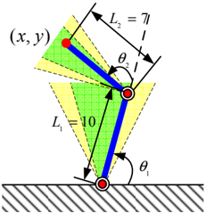
The image depicts a static mechanical linkage system consisting of two rods connected by a pivot joint. The system is analyzed within a coordinate plane (x, y), with geometric constraints defined by rod lengths (L₁, L₂) and angular positions (θ₁, θ₂). Shaded regions and striped patterns suggest motion boundaries or reference frames.
### Components/Axes
- **Axes**:
- Coordinate system labeled **(x, y)** at the top of the diagram.
- No explicit numerical scales for axes, but spatial relationships are defined by rod lengths and angles.
- **Legends/Colors**:
- **Blue**: Represents the two rigid rods (L₁ and L₂).
- **Green/Yellow**: Shaded regions, likely indicating motion ranges or stress zones.
- **Striped Pattern**: Background at the bottom, possibly representing a fixed ground plane.
- **Key Labels**:
- **L₁ = 10**: Length of the lower rod (blue).
- **L₂ = 7π/6**: Length of the upper rod (blue).
- **θ₁**: Angle between the lower rod and the horizontal ground.
- **θ₂**: Angle between the upper rod and the lower rod.
- **Red Dots**: Pivot points connecting the rods.
### Detailed Analysis
- **Rod Lengths**:
- L₁ = 10 (exact value).
- L₂ = 7π/6 ≈ 3.665 (approximate decimal value).
- **Angles**:
- θ₁ and θ₂ are marked but lack numerical values; their positions suggest θ₁ is measured from the ground to the lower rod, and θ₂ is the relative angle between the two rods.
- **Coordinate System**:
- The origin (0,0) is implied at the lower pivot point (bottom red dot).
- The red dot’s position (x, y) is determined by θ₁, θ₂, L₁, and L₂ via trigonometric relationships.
- **Shaded Regions**:
- Green and yellow areas likely represent allowable angular ranges for θ₁/θ₂ or stress distributions.
### Key Observations
1. **Geometric Constraints**:
- The system is a planar double pendulum-like structure, with motion confined to the (x, y) plane.
- The red dot’s position (x, y) is a function of θ₁ and θ₂, calculable using: