\n
## Diagram: Barrel Shifter Implementation
### Overview
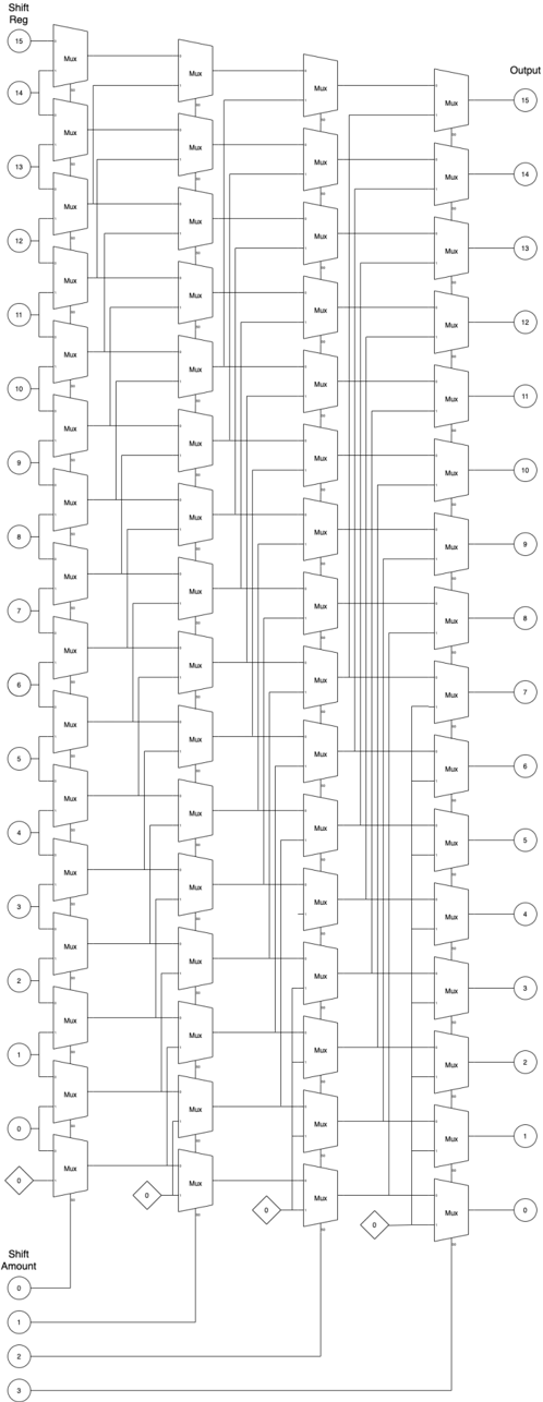
The image depicts a digital circuit diagram illustrating a barrel shifter implementation. The diagram shows a series of multiplexers (Mux) arranged to perform bitwise rotation or shifting of an input value. The shifter appears to be capable of shifting the input by a variable amount, controlled by the "Shift Amount" input.
### Components/Axes
The diagram consists of the following key components:
* **Shift Register (Input):** Labeled "Shift Reg" with values from 0 to 15, representing the input bits. These are positioned on the left side of the diagram.
* **Shift Amount:** Labeled "Shift Amount" with values from 0 to 3, representing the number of bits to shift. Located at the bottom-left.
* **Multiplexers (Mux):** Numerous rectangular blocks labeled "Mux" connecting the input bits to the output.
* **Output:** Labeled "Output" with values from 0 to 15, representing the shifted output bits. Positioned on the right side of the diagram.
* **Diamond Shapes:** These appear to represent selection logic, likely controlled by the "Shift Amount" input.
### Detailed Analysis
The diagram shows a 16-bit barrel shifter. The input bits (0-15) are connected to multiple multiplexers. Each multiplexer selects one of the input bits based on the "Shift Amount" signal. The output bits (0-15) are the result of this selection process.
Let's analyze the connections based on the shift amount:
* **Shift Amount = 0:** All output bits are directly connected to their corresponding input bits.
* **Shift Amount = 1:**
* Output 0 is connected to Input 15.
* Output 1 is connected to Input 0.
* Output 2 is connected to Input 1.
* ...and so on.
* **Shift Amount = 2:**
* Output 0 is connected to Input 14.
* Output 1 is connected to Input 15.
* Output 2 is connected to Input 0.
* ...and so on.
* **Shift Amount = 3:**
* Output 0 is connected to Input 13.
* Output 1 is connected to Input 14.
* Output 2 is connected to Input 15.
* Output 3 is connected to Input 0.
* ...and so on.
The diamond shapes act as selectors, directing the input signal to the appropriate output based on the "Shift Amount" value. The connections are arranged in a way that implements a circular shift.
### Key Observations
* The circuit implements a barrel shifter, which can perform shifts of 0, 1, 2, or 3 bits.
* The use of multiplexers allows for a parallel shift operation, making it faster than a serial shift.
* The circuit is designed for a 16-bit input.
* The diamond shapes are crucial for selecting the correct input based on the shift amount.
### Interpretation
This diagram illustrates a common hardware implementation of a barrel shifter. Barrel shifters are used in various digital systems for performing fast bitwise shifts and rotations. The circuit's structure allows for efficient shifting by selecting the appropriate input bit for each output bit based on the shift amount. The use of multiplexers enables parallel shifting, which is significantly faster than serial shifting. The circuit's modular design makes it scalable to different bit widths. The "Shift Amount" input provides flexibility in controlling the amount of shift, making it a versatile component in digital circuits. The diagram demonstrates a clear understanding of digital logic design principles and the implementation of arithmetic operations in hardware. The circuit is designed to perform a circular shift, meaning that bits shifted off one end are re-inserted at the other end. This is useful in applications where preserving the data is important, such as in cryptography or data compression.