## Circuit Diagram
### Overview
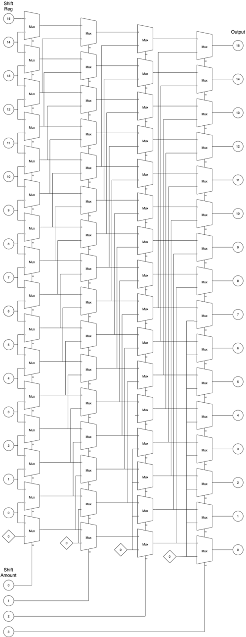
The image depicts a complex circuit diagram consisting of multiple components connected in a series of pathways. The diagram is labeled with various elements such as input, output, and intermediate nodes. The circuit appears to be a digital or electronic circuit, possibly related to signal processing or data transmission.
### Components/Axes
- **Input**: Located at the top left of the diagram, labeled "Shift Reg".
- **Output**: Located at the top right of the diagram, labeled "Output".
- **Intermediate Nodes**: Multiple nodes labeled "Mux" (Multiplexer) are connected in series, with each node receiving input from the previous one and sending output to the next.
- **Shift Amount**: A vertical axis on the left side of the diagram, labeled "Shift Amount", indicating the number of bits to shift the data.
### Detailed Analysis or ### Content Details
- **Multiplexer (Mux)**: Each "Mux" node is connected to the next, with the input signal passing through each Mux before reaching the output. The Muxes are labeled with numbers from 0 to 15, indicating the possible input signals.
- **Shift Amount**: The vertical axis on the left side of the diagram shows the shift amount, which is a binary number. The shift amount is used to determine the position of the data bits in the output signal.
- **Circuit Pathways**: The pathways between the Muxes and the output are clearly defined, with arrows indicating the direction of data flow.
### Key Observations
- **Data Shifting**: The circuit appears to be designed for data shifting, as indicated by the "Shift Reg" and "Shift Amount" labels.
- **Multiplexing**: The use of multiple Muxes suggests that the circuit is capable of selecting and routing multiple input signals to a single output.
- **Binary Shift**: The vertical axis on the left side of the diagram indicates that the data is being shifted in binary format.
### Interpretation
The circuit diagram represents a digital shift register circuit, which is used to shift data bits in a binary format. The circuit is designed to take an input signal, shift it by a specified amount, and output the shifted data. The use of multiple Muxes allows for the selection and routing of multiple input signals to the output, making the circuit versatile and capable of handling complex data processing tasks. The vertical axis on the left side of the diagram indicates that the data is being shifted in binary format, which is a common format for digital data transmission and processing.