## Diagram: Matrix Operation Visualization
### Overview
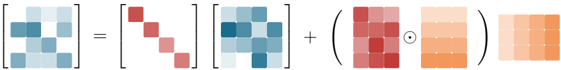
The image is a technical diagram illustrating a mathematical operation involving multiple matrices. It visually represents a formula where one matrix is expressed as the sum of a product of two matrices and the Hadamard (element-wise) product of two other matrices. The diagram uses color-coded cells within the matrices to represent numerical values, with a gradient from blue (likely representing lower or negative values) to red (likely representing higher or positive values).
### Components/Axes
The diagram is composed of five distinct matrix components and mathematical operators arranged horizontally from left to right.
1. **Leftmost Matrix (Result):** A 4x4 grid of cells. The cells are colored in various shades of blue, with some cells darker than others. This matrix is the subject of the equation.
2. **Equals Sign (`=`):** Separates the result matrix from the expression that defines it.
3. **First Matrix in Expression:** A 4x4 grid. Its diagonal cells (from top-left to bottom-right) are colored in shades of red, while all off-diagonal cells are a neutral light gray/white. This suggests a diagonal matrix.
4. **Multiplication Operator (Implied):** The second matrix is placed directly after the first, implying matrix multiplication.
5. **Second Matrix in Expression:** A 4x4 grid. Its cells are colored in various shades of blue, similar to the leftmost result matrix.
6. **Plus Sign (`+`):** Indicates the addition of the next term.
7. **Hadamard Product Term:** This term is enclosed in parentheses and consists of:
* **Left Matrix:** A 4x4 grid with cells colored in shades of red.
* **Hadamard Product Symbol (`⊙`):** A circle with a dot in the center, denoting element-wise multiplication.
* **Right Matrix:** A 4x4 grid with cells colored in a gradient from light orange/peach on the left to a darker orange on the right.
8. **Final Matrix (Output of Hadamard Product):** A 4x4 grid positioned to the right of the parentheses. Its cells are colored in a uniform light orange/peach, matching the leftmost column of the right matrix inside the parentheses.
### Detailed Analysis
* **Spatial Layout:** The entire equation flows linearly from left to right. The Hadamard product sub-expression is grouped visually by parentheses.
* **Color Coding & Value Inference:**
* **Blue Matrices (Leftmost and Second in Expression):** The distribution of dark and light blue cells appears similar but not identical between these two matrices. The leftmost matrix has a cluster of darker blue cells in the top-left quadrant. The second matrix has a more scattered pattern of dark blue cells.
* **Red Diagonal Matrix:** The strong red diagonal is a clear visual indicator of a diagonal matrix structure, where only the elements `M[i,i]` are non-zero.
* **Red and Orange Matrices in Hadamard Product:** The left matrix is entirely red-toned. The right matrix has a horizontal color gradient. Their element-wise product results in the final, uniformly light-orange matrix. This suggests the red matrix might be a mask or scaling factor applied to the gradient matrix.
* **Matrix Dimensions:** All five matrices shown are 4x4 grids.
### Key Observations
1. **Structural Decomposition:** The diagram visually decomposes the leftmost blue matrix into two distinct components: a product of a diagonal red matrix and another blue matrix, plus a separate term derived from a Hadamard product.
2. **Color as Data Proxy:** The consistent use of color gradients (blue scale, red scale, orange gradient) implies that color intensity is used to represent the magnitude of numerical values within the matrices.
3. **Operator Clarity:** The use of standard mathematical symbols (`=`, `+`, `⊙`) and spatial grouping (parentheses) makes the operational flow unambiguous despite the lack of textual labels.
4. **Potential Context:** This visual style is common in explanations of neural network operations, matrix factorization techniques, or attention mechanisms in machine learning, where matrices represent weights, activations, or gates.
### Interpretation
This diagram is a purely visual representation of a matrix equation, likely from a technical paper or presentation in the field of linear algebra or machine learning. It demonstrates how a target matrix (left) can be constructed or approximated through a specific combination of operations.
* **What it Suggests:** The equation `Result = (Diagonal Matrix * Blue Matrix) + (Red Matrix ⊙ Orange Gradient Matrix)` implies a model where the final output has two parts: a transformed version of a base matrix (the blue one, modulated by a diagonal scaling or selection matrix) and an additional, spatially varying (due to the gradient) correction or feature map that is element-wise gated or scaled by the red matrix.
* **Relationships:** The Hadamard product term appears to be an additive correction or refinement to the primary matrix product term. The uniform color of the final orange matrix suggests the operation within the parentheses results in a matrix with relatively homogeneous values.
* **Anomalies/Notable Points:** The most striking visual element is the stark red diagonal matrix, which immediately draws attention to the importance of diagonal operations in this formula. The lack of any numerical labels or axis titles means the exact values and their meanings are abstract; the diagram communicates structure and relational logic rather than specific data points. The interpretation relies entirely on the viewer's familiarity with the symbolic conventions of matrix algebra.