## Block Diagram: Neural Network Accelerator Architecture
### Overview
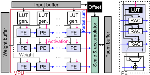
The image depicts a technical block diagram of a neural network accelerator architecture, divided into two primary sections:
1. **Left Diagram**: A high-level overview of the system's data flow and processing units.
2. **Right Diagram**: A zoomed-in view of the Look-Up Table (LUT) and Reconfigurable Array Controller (RAC) components.
---
### Components/Axes
#### Left Diagram Labels:
- **Top**: Input Buffer (gray)
- **Left**: Weight Buffer (gray)
- **Central Blocks**:
- LUT Generators (labeled "LUT gen.")
- Processing Elements (PEs) arranged in rows
- Partial Sum (blue arrow)
- Scale & Accumulator (green block)
- Output Buffer (gray)
- **Right**: Offset (black block)
- **Arrows**:
- Red: Activation signals
- Blue: Weight signals
- Gray: Data flow between buffers
- Pink: Offset input
#### Right Diagram Labels:
- **Top**: LUT (black block)
- **Middle**: Three stacked RAC blocks (purple)
- **Bottom**: PE (blue arrow)
- **Arrows**:
- Blue: Data flow between RACs and PE
- Pink: Feedback loop from PE to RAC
#### Legend:
- **Colors**:
- Red: Activation
- Blue: Weight
- Green: Partial Sum
- Gray: Buffers
- Black: LUT
- Purple: RAC
- Pink: Offset
---
### Detailed Analysis
#### Left Diagram:
1. **Data Flow**:
- Input data enters the Input Buffer and is distributed to LUT Generators.
- LUT Generators produce weights, which are fed into PEs along with Activation signals (red arrows).
- PEs process data and generate Partial Sums (blue arrows), which are scaled and accumulated in the Scale & Accumulator block.
- Final output is stored in the Output Buffer.
2. **Key Connections**:
- Weight signals (blue) originate from the Weight Buffer and are routed to PEs.
- The Offset (pink) is injected into the Partial Sum path.
#### Right Diagram:
1. **LUT and RAC Structure**:
- The LUT (black) feeds into three RAC blocks (purple), which are connected in a feedback loop.
- The PE (blue arrow) receives input from the RACs and sends output back to the RACs via a feedback path.
2. **Functional Role**:
- The RACs likely perform reconfigurable computations (e.g., matrix operations) for neural network layers.
- The feedback loop suggests iterative processing or error correction.
---
### Key Observations
1. **Modular Design**:
- The architecture emphasizes modularity, with distinct blocks for LUTs, RACs, and PEs.
- Buffers (Input/Weight/Output) ensure data staging and synchronization.
2. **Parallelism**:
- Multiple PEs and LUT Generators suggest parallel processing capabilities.
3. **Feedback Mechanism**:
- The right diagram’s feedback loop (pink arrow) indicates dynamic adjustment or iterative computation.
4. **Signal Paths**:
- Activation (red) and Weight (blue) signals are clearly separated, reducing cross-talk.
---
### Interpretation
This diagram represents a hardware accelerator optimized for neural network computations. The left diagram highlights the system’s data flow, emphasizing parallelism through PEs and LUT Generators. The right diagram zooms into the LUT and RAC components, revealing a reconfigurable processing unit with feedback for adaptive computations.
- **Functional Insights**:
- The Scale & Accumulator block likely handles quantization and bias addition, critical for low-precision neural network inference.
- The feedback loop in the RACs may enable dynamic weight updates or error propagation, improving model accuracy.
- **Design Implications**:
- The use of PEs and RACs suggests a focus on energy efficiency and throughput, typical of edge AI hardware.
- The separation of Activation and Weight signals simplifies timing constraints and reduces power consumption.
- **Potential Limitations**:
- The diagram does not specify clock frequencies or latency, which are critical for real-world performance.
- The absence of error-handling mechanisms (e.g., fault tolerance) raises questions about robustness in noisy environments.
This architecture balances modularity and performance, making it suitable for applications like real-time image recognition or autonomous systems.