## Diagram: Gear and Belt System
### Overview
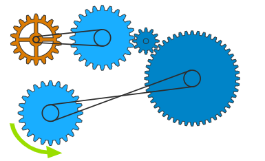
The image depicts a system of gears and belts designed to transmit rotational motion. It includes gears of varying sizes and belts connecting them, illustrating how the rotation of one gear can drive others. A green arrow indicates the direction of rotation for one of the gears.
### Components/Axes
* **Gears:** Several gears are present, varying in size and color (orange and blue).
* **Belts:** Black belts connect some of the gears, transmitting rotational motion.
* **Rotation Arrow:** A green curved arrow indicates the direction of rotation for one of the blue gears.
### Detailed Analysis
The system can be broken down into two main sections:
1. **Top Section:**
* A small orange gear on the top-left is connected via a belt to a larger blue gear.
* This larger blue gear is connected to a smaller blue gear via direct contact (meshing).
* The smaller blue gear is connected to a very large blue gear via direct contact (meshing).
2. **Bottom Section:**
* A blue gear is connected via a crossed belt to a very large blue gear.
* A green arrow indicates that the blue gear rotates counter-clockwise.
### Key Observations
* The crossed belt in the bottom section indicates that the direction of rotation of the two gears connected by the belt will be opposite.
* The gears in the top section are connected in a way that allows for changes in speed and torque.
* The size differences between the gears suggest changes in rotational speed and torque.
### Interpretation
The diagram illustrates a mechanical system designed to transmit and modify rotational motion. The use of different sized gears and belts allows for changes in speed and torque. The crossed belt in the bottom section demonstrates a method for reversing the direction of rotation. The system demonstrates basic principles of mechanical power transmission.