## [Diagram Type]: Mechanical Gear and Belt Transmission System
### Overview
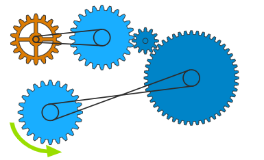
This image is a technical diagram illustrating a mechanical power transmission system. It consists of five distinct gears (toothed wheels) of varying sizes and colors, interconnected by two belt drives and two direct gear meshes. A green arrow at the bottom-left indicates the input direction of rotation.
### Components/Axes
The system is composed of the following elements, identified by their spatial position and visual characteristics:
* **Gear 1 (Top-Left):** An orange, medium-sized gear with a central pulley.
* **Gear 2 (Top-Middle):** A large, light-blue gear with a central pulley.
* **Gear 3 (Top-Right):** A small, light-blue gear.
* **Gear 4 (Bottom-Right):** A large, dark-blue gear with a central pulley.
* **Gear 5 (Bottom-Left):** A medium-sized, light-blue gear with a central pulley.
* **Belt 1 (Top):** An open belt connecting the central pulley of Gear 1 to the central pulley of Gear 2.
* **Belt 2 (Bottom):** A crossed belt connecting the central pulley of Gear 5 to the central pulley of Gear 4.
* **Rotation Indicator:** A green, curved arrow located at the bottom-left, adjacent to Gear 5.
### Detailed Analysis
The system functions as a kinematic chain. The flow of motion can be traced as follows:
1. **Input:** The system is driven by **Gear 5** (bottom-left). The green arrow indicates a **counter-clockwise (CCW)** rotation.
2. **Belt 2 (Crossed):** Gear 5 is connected to **Gear 4** (bottom-right) via a crossed belt. Because the belt is crossed, the direction of rotation is reversed between the two pulleys.
* *Result:* Gear 4 rotates **clockwise (CW)**.
3. **Mesh 1:** Gear 4 is meshed directly with **Gear 3** (top-right). Meshed gears rotate in opposite directions.
* *Result:* Gear 3 rotates **counter-clockwise (CCW)**.
4. **Mesh 2:** Gear 3 is meshed directly with **Gear 2** (top-middle).
* *Result:* Gear 2 rotates **clockwise (CW)**.
5. **Belt 1 (Open):** Gear 2 is connected to **Gear 1** (top-left) via an open belt. An open belt maintains the direction of rotation between the two pulleys.
* *Result:* Gear 1 rotates **clockwise (CW)**.
### Key Observations
* **Directional Logic:** The system demonstrates how to manipulate rotational direction using different coupling methods. The crossed belt (Belt 2) acts as a direction inverter, while the open belt (Belt 1) acts as a direction transmitter.
* **Mechanical Advantage:** The system utilizes gears of different diameters (e.g., the large Gear 2 vs. the small Gear 3), which implies changes in torque and rotational speed (RPM) throughout the chain.
* **Color Coding:** The color coding (Orange vs. Light Blue vs. Dark Blue) appears to distinguish between different sub-assemblies or perhaps different stages of the transmission, though it does not explicitly denote material properties.
### Interpretation
This diagram serves as a fundamental lesson in mechanical engineering kinematics. It demonstrates the relationship between input and output motion in a complex train.
* **The Crossed Belt Effect:** The most critical component for directional control is the crossed belt between Gear 5 and Gear 4. Without this crossing, the entire system's rotational direction would be inverted.
* **The Meshing Effect:** The two points of contact between Gear 4/3 and Gear 3/2 create a "gear train" that transmits motion across a vertical gap.
* **System Integrity:** The diagram illustrates a closed-loop logic where the input at the bottom-left (Gear 5) dictates the final output at the top-left (Gear 1). If the input (Gear 5) were to stop, the entire chain would lock due to the rigid connections of the meshes and the tension of the belts. This is a classic example of a compound transmission system used to relocate power from one spatial coordinate to another while simultaneously adjusting rotational speed and direction.