\n
## Diagram: Gear and Belt System
### Overview
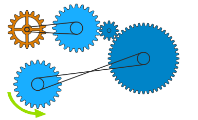
The image depicts a mechanical system composed of gears connected by belts. The system appears to demonstrate a method of transmitting rotational motion between gears of varying sizes. There are no numerical values or labels present, making a quantitative analysis impossible. The diagram focuses on the arrangement and interconnection of the components.
### Components/Axes
The diagram consists of the following components:
* **Gears:** Five gears are visible, varying in size. One gear is colored orange, and the remaining four are blue.
* **Belts:** Four belts connect the gears, transmitting rotational force.
* **Arrow:** A green arrow indicates the direction of rotation for one of the gears.
There are no axes or scales present in the image.
### Detailed Analysis or Content Details
The system can be described as follows:
1. **Top-Left Gear (Orange):** This gear is the smallest in the system and appears to be the initial driver.
2. **Top-Center Gear (Blue):** Connected to the orange gear via a belt. It is larger than the orange gear.
3. **Top-Right Gear (Blue):** Connected to the top-center gear via a belt. It is smaller than the top-center gear.
4. **Bottom-Left Gear (Blue):** Connected to the orange gear via a belt. It is the largest gear in the system.
5. **Bottom-Right Gear (Blue):** Connected to the bottom-left gear via a belt. It is similar in size to the top-center gear.
The green arrow, positioned near the bottom-left gear, indicates a counter-clockwise rotation. The belts are depicted as straight lines connecting the centers of the gears.
### Key Observations
* The system utilizes a combination of gear sizes and belt connections to potentially alter the speed and torque of the rotational motion.
* The orange gear appears to be the input, driving the other gears through the belt system.
* The bottom-left gear is significantly larger than the orange gear, suggesting a potential torque amplification.
* The arrangement of belts and gears suggests a complex transmission of rotational force.
### Interpretation
The diagram illustrates a basic mechanical power transmission system. The varying sizes of the gears and the belt connections imply that the system is designed to modify the rotational speed and torque. The larger gear (bottom-left) driven by the smaller gear (orange) suggests a torque increase, while the smaller gear (top-right) driven by the larger gear (top-center) suggests a speed increase. The system demonstrates a fundamental principle of mechanical engineering: using gears and belts to manipulate rotational motion for specific applications. Without numerical data on gear tooth counts or belt lengths, it is impossible to quantify the exact speed and torque ratios. The diagram serves as a conceptual illustration rather than a precise engineering specification.