## Gear System Diagram: Mechanical Power Transmission
### Overview
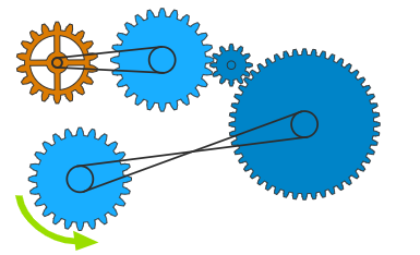
The image depicts a mechanical gear system with five interconnected gears. The system includes one brown gear, three blue gears of varying sizes, and one dark blue gear. Chains connect the gears, and a green arrow indicates rotational direction. No textual labels or legends are present.
### Components/Axes
- **Gears**:
- **Brown Gear**: Smallest gear, positioned at the top-left.
- **Large Blue Gear**: Central gear, largest in size, located at the top-right.
- **Medium Blue Gear**: Positioned between the brown and large blue gears.
- **Small Blue Gear**: Located near the large blue gear, smaller than the medium blue gear.
- **Bottom Blue Gear**: Largest blue gear, positioned at the bottom-right.
- **Chains**: Black lines connecting gears.
- **Rotation Indicator**: Green arrow at the bottom-left, showing clockwise rotation of the bottom blue gear.
### Detailed Analysis
- **Connections**:
- The brown gear is connected via a chain to the large blue gear.
- The medium blue gear is connected to both the brown and large blue gears.
- The small blue gear is connected to the large blue gear.
- The bottom blue gear is connected to the large blue gear.
- **Rotation Dynamics**:
- The green arrow indicates the bottom blue gear rotates clockwise.
- Connected gears will rotate in opposite directions (e.g., if the bottom blue gear turns clockwise, the large blue gear turns counterclockwise).
- **Size Relationships**:
- The large blue gear is approximately 3x the diameter of the brown gear.
- The medium blue gear is ~1.5x the diameter of the small blue gear.
### Key Observations
1. The system forms a closed loop via chain connections, suggesting synchronized motion.
2. The brown gear’s small size implies it may act as a driver for higher-speed, lower-torque output.
3. The large blue gear’s central position suggests it transmits power to multiple subsystems.
4. No explicit numerical data (e.g., gear ratios, torque values) is provided.
### Interpretation
This diagram illustrates a basic gear train for mechanical power transmission. The absence of labels implies the focus is on spatial relationships and motion direction. The green arrow’s indication of clockwise rotation for the bottom blue gear allows inference of rotational directions for other gears:
- **Bottom Blue Gear (Clockwise)** → **Large Blue Gear (Counterclockwise)** → **Medium/Small Blue Gears (Clockwise)** → **Brown Gear (Counterclockwise)**.
The system likely demonstrates trade-offs between speed and torque, with smaller gears (e.g., brown) increasing rotational speed at the expense of force, while larger gears (e.g., large blue) reduce speed but amplify torque.
No textual data or numerical values are present in the image. The analysis is based solely on visual spatial relationships and mechanical principles.