## System Architecture and Process Flow Diagrams
### Overview
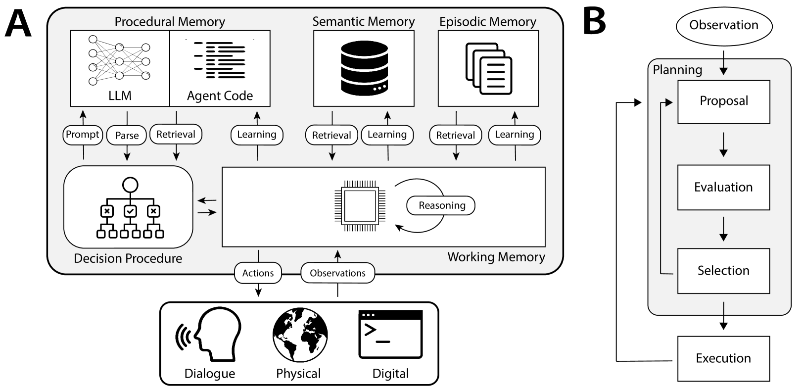
The image contains two interconnected diagrams (A and B) depicting a cognitive system architecture and its operational workflow. Diagram A illustrates memory systems, decision-making processes, and interaction modalities, while Diagram B outlines a sequential decision-making process with feedback loops.
### Components/Axes
#### Diagram A: Cognitive System Architecture
1. **Procedural Memory**
- Contains LLM (Language Learning Model) and Agent Code
- Processes: Prompt → Parse → Retrieval → Learning
2. **Semantic Memory**
- Database icon with Retrieval → Learning feedback
3. **Episodic Memory**
- Document stack icon with Retrieval → Learning feedback
4. **Decision Procedure**
- Flowchart with three decision nodes (X, ✓, X) leading to Actions/Obs
5. **Working Memory**
- CPU icon with bidirectional Reasoning loop
6. **Interaction Modalities**
- Dialogue (speech bubble), Physical (globe), Digital (code editor)
#### Diagram B: Decision Process Workflow
1. **Process Steps**
- Observation → Planning → Proposal → Evaluation → Selection → Execution
2. **Feedback Loop**
- Execution → Planning (dashed arrow)
### Detailed Analysis
**Diagram A Components:**
- **Memory Systems**: All memory types (procedural, semantic, episodic) share identical feedback loops (Retrieval → Learning), suggesting iterative knowledge refinement.
- **Decision Procedure**: Binary outcomes (X/✓) imply probabilistic decision-making with error correction.
- **Working Memory**: Central CPU icon with Reasoning loop indicates active processing of sensory inputs (Actions/Obs).
**Diagram B Workflow:**
- Linear progression from Observation to Execution with explicit feedback from Execution to Planning.
- No parallel processing paths; strictly sequential decision-making.
### Key Observations
1. **Memory Integration**: All memory types converge on Working Memory through Reasoning, creating a unified cognitive processing hub.
2. **Error Handling**: Decision Procedure includes explicit error nodes (X marks), suggesting built-in failure analysis.
3. **Modality Triad**: Dialogue/Physical/Digital icons represent input/output channels for the system.
4. **Feedback Criticality**: Diagram B's feedback loop from Execution to Planning enables adaptive learning.
### Interpretation
This architecture represents an embodied cognitive system where:
1. **Memory Hierarchy**: Episodic (experiential) and Semantic (factual) memories inform Procedural Memory (skills), creating a layered knowledge base.
2. **Decision-Making**: The system combines probabilistic reasoning (Decision Procedure) with continuous learning (feedback loops), mirroring human cognitive processes.
3. **Embodiment**: The triad of interaction modalities (Dialogue/Physical/Digital) suggests a multimodal AI agent capable of interacting with physical/digital environments and human users.
4. **Process Optimization**: The strict sequential workflow in Diagram B with feedback loops creates a closed-loop system for continuous improvement.
The diagrams collectively illustrate an artificial general intelligence framework combining memory systems, probabilistic reasoning, and embodied interaction. The absence of quantitative metrics suggests this is a conceptual rather than empirical model.